Method for forming liquid cavity through adding of multi-part middle spacing sleeve

A petal type and spacer technology, which is applied in the direction of mechanical equipment, shock absorbers, springs, etc., can solve the problems of large wheel rail and line wear, small stiffness performance, and high maintenance costs, and achieve optimal product performance, small radial stiffness, The effect of improving reliability

Inactive Publication Date: 2019-11-22
ZHUZHOU TIMES RUIWEI ANTI VIBERATION EQUIP LTD
View PDF12 Cites 4 Cited by
  • Summary
  • Abstract
  • Description
  • Claims
  • Application Information

AI Technical Summary

Problems solved by technology

[0002] According to the dynamic requirements, when the pivoting arm node is running in a straight line at high speed (high frequency vibration), it provides a large radial stiffness to ensure the running stability and increase the critical speed; when it passes the curve (low frequency and large amplitude), it provides a small stiffness performance Guarantee over-curve performance and reduce wear; it is difficult for ordinary joints to achieve the above characteristics, especially for old lines, where the wear of wheels, rails and lines is high, and the maintenance cost is high. Therefore, it is necessary to use a new product that has the above characteristics at the same time—liquid rubber composite joints

Method used


Image

  • Method for forming liquid cavity through adding of multi-part middle spacing sleeve
  • Method for forming liquid cavity through adding of multi-part middle spacing sleeve
  • Method for forming liquid cavity through adding of multi-part middle spacing sleeve

Examples


Embodiment 1

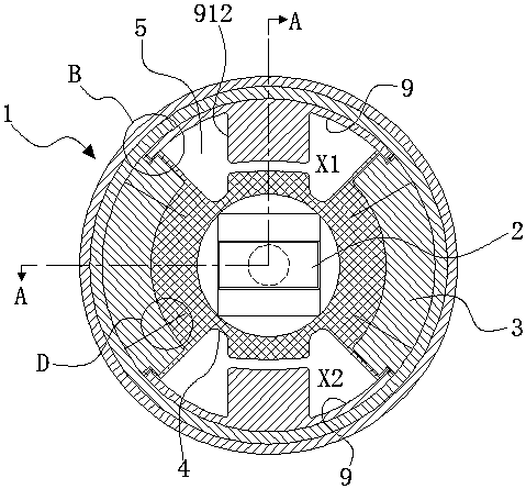
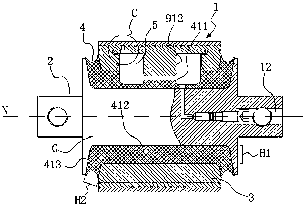
[0041] Embodiment 1: as figure 1 with figure 2 As shown, the liquid rubber composite node involved in the present invention includes an outer jacket 1, a mandrel 2 and a multi-lobed middle spacer 3 between the outer jacket 1 and the mandrel 2, and the multi-lobed middle spacer 3 and the mandrel 2. Bond together by vulcanization of rubber 4, and then assemble the integrated multi-lobed middle spacer and mandrel into the outer casing 1; set the flow channel in the outer casing 1, and hollow out the multi-lobe middle spacer 3 to form A plurality of spaces, when vulcanized, utilize rubber 4 and the plurality of spaces to form a plurality of liquid cavities 5 independent of each other, liquid (not shown in the figure) is arranged in the plurality of liquid cavities 5 and the plurality of liquid cavities The cavities 5 are connected through flow channels.

[0042] A method of forming a liquid cavity by adding a multi-lobed intermediate spacer provided in this embodiment is to hol...

Embodiment 2

[0058] Embodiment 2: as Figure 9 As shown, compared with Embodiment 1, the difference is that in this embodiment, a two-petal intermediate spacer 3 is used, including an upper arc-shaped petal body 313 and a lower arc-shaped petal body 314 .

Embodiment 3

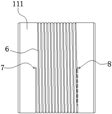
[0059] Embodiment 3: as Figure 10 to Figure 12 As shown, compared with Embodiment 1, the difference lies in that the design structure of the flow channel is different. In this embodiment, the flow channel is formed as follows: the mandrel 2 is divided into inner and outer parts, the inner part is the mandrel body 212, and the outer part is the mandrel jacket 213, and the mandrel body 212 is interference fitted to the mandrel jacket 213 in. Runner grooves 6 are arranged on the outer peripheral surface of the mandrel body 212, and the runner grooves 6 are spirally distributed on the outer peripheral surface of the mandrel body 212. Here, the runner grooves 6 may not be spirally surrounded, Instead it is set in other shape. When the mandrel body 212 is interference-fitted into the mandrel outer cover 213, the inner peripheral surface of the mandrel outer cover 213 is used to block and seal the notch of the flow channel groove 6 to form an inner groove flow channel, so that the...


PUM


Abstract

The invention discloses a method for forming a liquid cavity through adding of a multi-part middle spacing sleeve. Firstly, the multi-part middle spacing sleeve is additionally arranged between a mandrel and an outer sleeve; then, the multi-part middle spacing sleeve is hollowed to form multiple space; the multi-park middle spacing sleeve and the mandrel are bonded through rubber vulcanization; and multiple independent liquid cavities are formed by using rubber and the multi-part middle spacing sleeve. The method can provide lower radial rigidity and higher axial rigidity to realize a higher dynamic-static ratio to optimize the product performances of liquid rubber compound nodes.

Description

technical field [0001] The invention relates to a method for forming a liquid cavity in a liquid rubber composite node, in particular to a method for forming a liquid cavity by adding a multi-lobed intermediate spacer sleeve. Background technique [0002] According to the dynamic requirements, when the pivoting arm node is running in a straight line at high speed (high frequency vibration), it provides a large radial stiffness to ensure the running stability and increase the critical speed; when it passes the curve (low frequency and large amplitude), it provides a small stiffness performance Guaranteed over-curve performance and reduced wear; it is difficult for ordinary joints to achieve the above characteristics, especially for old lines, where wheel rails and lines wear a lot, and the maintenance cost is high. Therefore, it is necessary to use a new product that has the above characteristics at the same time—liquid rubber composite joints. [0003] The working principle ...

Claims


Application Information

Patent Timeline
Patent Type & Authority Applications(China)
IPC IPC(8): F16F13/18
CPCF16F13/18
Inventor 王健罗俊陈俊辉李静黄江彪张玉祥张志强曾慧
Owner ZHUZHOU TIMES RUIWEI ANTI VIBERATION EQUIP LTD
Why Eureka
Try Eureka