Eureka AIR delivers breakthrough ideas for toughest innovation challenges, trusted by R&D personnel around the world.

A three-workstation j-type laying system

A technology for workstations and laying devices, applied in pipeline laying and maintenance, mechanical equipment, pipes/pipe joints/fittings, etc., can solve the problem that J-shaped towers cannot perform welding, non-destructive testing and coating operations at the same time, and increase J-shaped laying systems Problems such as the overall overall weight and the heavy weight of the J-shaped laying system achieve the effects of ensuring laying efficiency, improving laying efficiency, and simplifying the laying process

Active Publication Date: 2021-06-29
OFFSHORE OIL ENG CO LTD +1
View PDF4 Cites 0 Cited by
  • Summary
  • Abstract
  • Description
  • Claims
  • Application Information

AI Technical Summary

Problems solved by technology

[0005] (1) The J-type laying system is heavy. For the J-type laying system with one or two workstations, in order to improve its laying efficiency, the number of pipe sections must be increased, which leads to a higher J-shaped tower and a larger weight of the pipe section transmission equipment , increasing the overall overall weight of the J-lay system
[0006] (2) The laying efficiency is low, welding, non-destructive testing and coating operations cannot be carried out on the J-shaped tower at the same time, which reduces the efficiency of J-shaped laying. At the same time, a variety of equipment is arranged in one workstation to increase the laying process

Method used


Image

  • A three-workstation j-type laying system
  • A three-workstation j-type laying system
  • A three-workstation j-type laying system

Examples


Embodiment Construction

[0028] Embodiments of the present invention are described in detail below, examples of which are shown in the drawings, wherein the same or similar reference numerals designate the same or similar elements or elements having the same or similar functions throughout. The embodiments described below by referring to the figures are exemplary and are intended to explain the present invention and should not be construed as limiting the present invention.

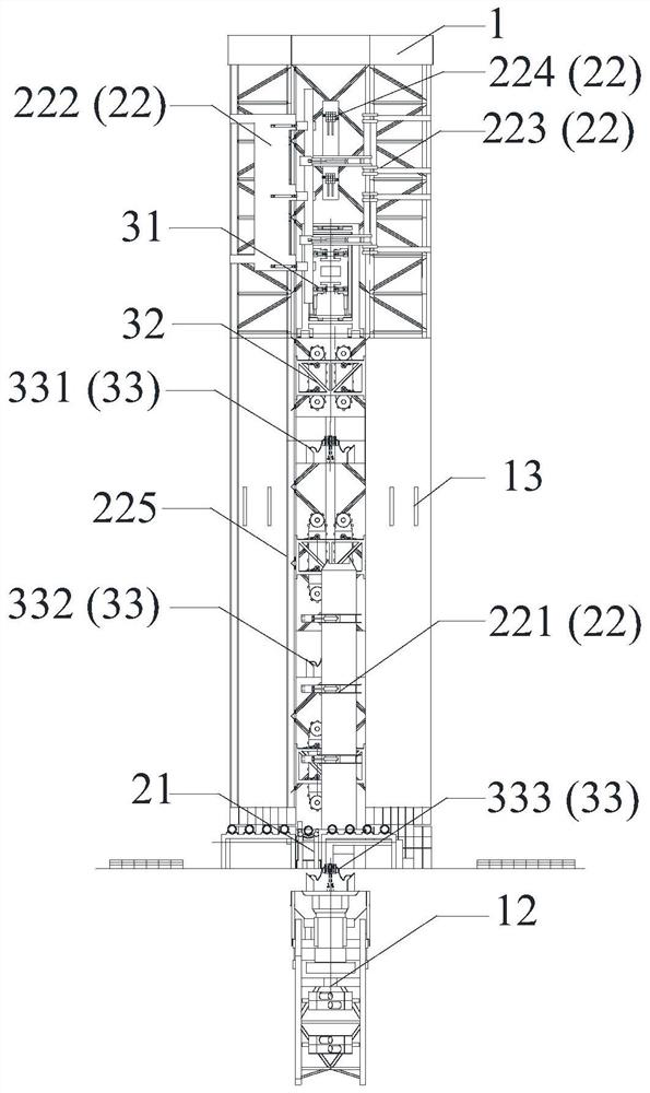
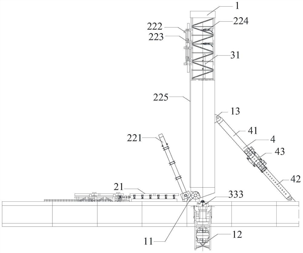
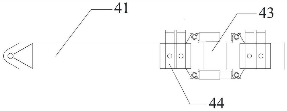
[0029] Such as Figure 1 to Figure 4 As shown, according to a specific embodiment of the present invention, a three-workstation J-type laying system includes: J-type tower 1, pipeline delivery device 2, pipeline laying device 3 and angle adjustment assembly 4, J-type tower 1 and hull deck Rotating connection, the pipeline conveying device 2 is used to move the pipe section to be laid from the deck to the inside of the J-shaped tower 1. The pipeline conveying device 2 includes a horizontal conveying assembly 21 and a vertical uppe...


PUM


Abstract

The invention discloses a three-workstation type J-type laying system, comprising: a J-type tower, a pipeline conveying device, a pipeline laying device and an angle adjustment assembly, the J-type tower is rotatably connected with the hull deck, and the pipeline conveying device is used for laying the pipe section Move from the deck to the inside of the J-shaped tower. The pipeline conveying device includes a horizontal conveying assembly and a vertical upper pipe assembly. The horizontal conveying assembly is laid on the deck. The pipeline elevator, rotating arm and vertical pipe wheel; the pipeline laying device is arranged on the J-shaped tower; the two ends of the angle adjustment component are respectively hinged with the J-shaped tower and the deck to adjust the angle of the J-shaped tower. The J-shaped laying system of the present invention arranges three workstations to realize simultaneous welding, non-destructive testing and coating operations of three-section and two-node pipes, greatly improving the laying efficiency, and repairing welding of unqualified parts in time after the completion of non-destructive monitoring. Simplify the laying process and reduce the laying cost.

Description

technical field [0001] The invention relates to the technical field of submarine pipeline and riser laying, in particular to a three-workstation J-shaped laying system. Background technique [0002] As the development of marine resources continues to develop towards deep water, the difficulty of laying deep-water submarine pipelines will increase, and at the same time, higher requirements will be placed on pipe-laying ships. At present, there are four mature pipeline laying methods in the field of marine engineering: S-type laying, J-type laying, reel laying, and towed laying. Among them, J-shaped laying uses J-shaped towers to lay pipelines into the water in a nearly vertical state, reducing The bending stress at the water inlet of the pipeline and the tension on the pipeline during the laying process have good deep water adaptability, and are considered to be the most suitable method for deep water pipeline laying. [0003] At present, the heavy-duty J-type pipe-laying ve...

Claims


Application Information

Patent Timeline
Patent Type & Authority Patents(China)
IPC IPC(8): F16L1/16F16L1/19F16L1/20F16L1/23
CPCF16L1/161F16L1/19F16L1/206F16L1/207F16L1/23
Inventor 钟文军康庄何宁彭小佳张法富马刚赵党艾尚茂王辉李少杰
Owner OFFSHORE OIL ENG CO LTD
Why Eureka
Eureka Blog
Learn More