Optical axis consistency adjustment and detection device and method for space laser communication terminal
A laser communication and detection device technology, applied in the field of optical detection, can solve the problems of high dependence on operator skills and proficiency, long assembly and adjustment cycle, low assembly efficiency, etc., to achieve simple and fast assembly, adjustment and detection, and convenient installation and operation , The effect of high adjustment accuracy
- Summary
- Abstract
- Description
- Claims
- Application Information
AI Technical Summary
Problems solved by technology
Method used
Image
Examples
Embodiment 1
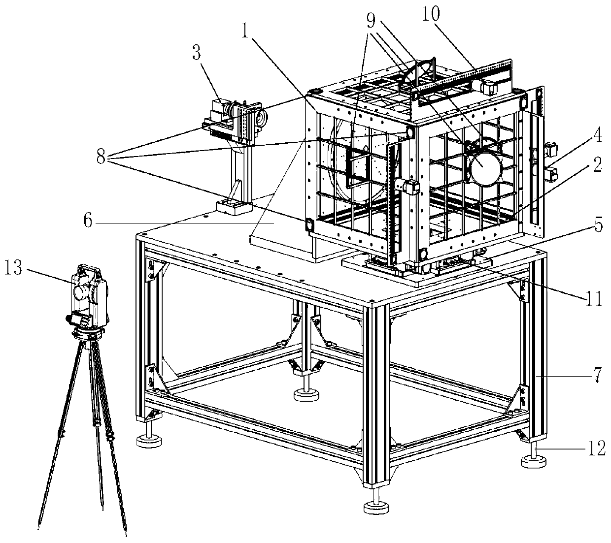
[0067] Such as Figure 7 As shown, the optical system to be installed and adjusted in the optical system of the laser communication terminal is the signal light emitting system 144, and the above-mentioned optical axis consistency detection device for the space laser communication terminal is used to control the signal light emitting system 144 to be installed and adjusted. The optical axis consistency of the lens is adjusted, and the steps are the same as the above method. The specific step four is:
[0068] Turn on the low-divergence angle light source 3, the self-collimated laser light emitted by the low-divergence angle light source 3 is incident from the entrance of the laser communication terminal 14 to be installed and adjusted, and exits from the signal light emitting system 144 in the laser communication terminal 14 to be installed and adjusted, and then passes through the laser communication terminal 14 to be installed and adjusted. The reflector 9 on the detection b...
Embodiment 2
[0070] Such as Figure 8 As shown, the optical system to be adjusted in the optical system of the laser communication terminal is the second signal light receiving system 150, and the above-mentioned optical axis consistency detection device for the space laser communication terminal is used to detect the second signal light to be adjusted. The optical axis alignment of the lens of the receiving system 150 is adjusted, and the steps are the same as the above-mentioned method, and the specific step four is:
[0071] Turn on the low-divergence angle light source 3, and the self-collimated laser light emitted by the low-divergence angle light source 3 is incident from the entrance of the laser communication terminal 14 to be installed and adjusted, and exits from the second signal light receiving system 150 in the laser communication terminal 14 to be installed and adjusted. The reflector 9 on the detection board 1 on the front side of the detection board installation frame 2 cor...
Embodiment 3
[0074] Such as Figure 9 As shown, the optical system to be adjusted in the optical system of the laser communication terminal is the first signal light receiving system 145, and the first signal light to be adjusted is detected by the above-mentioned optical axis consistency detection device for the space laser communication terminal. The method for adjusting the lens of the receiving system 145 for optical axis consistency is the same as the above-mentioned method, and the specific step four is:
[0075] Turn on the low-divergence angle light source 3, and the self-collimated laser light emitted by the low-divergence angle light source 3 is incident from the entrance of the laser communication terminal 14 to be installed and adjusted, and is emitted from the first signal light receiving system 145 in the laser communication terminal 14 to be installed and adjusted. The reflector 9 on the detection board 1 on the right side of the detection board installation frame 2 correspo...
PUM
 Abstract
Description
Claims
Application Information
 - R&D
- Intellectual Property
- Life Sciences
- Materials
- Tech Scout
- Unparalleled Data Quality
- Higher Quality Content
- 60% Fewer Hallucinations
Browse by: Latest US Patents, China's latest patents, Technical Efficacy Thesaurus, Application Domain, Technology Topic, Popular Technical Reports.
© 2025 PatSnap. All rights reserved.Legal|Privacy policy|Modern Slavery Act Transparency Statement|Sitemap|About US| Contact US: help@patsnap.com


