
A standing wave resonance aging device and method for a high power input coupler

A technology of input coupling and high power, applied in the field of mature standing wave resonance devices, can solve the problems of low power gain, complex structure, and inability to form complete standing wave resonance, etc., and achieve the effect of improving power gain, easy operation, and simple and reliable structure

Active Publication Date: 2021-06-01
INST OF MODERN PHYSICS CHINESE ACADEMY OF SCI
View PDF8 Cites 0 Cited by
  • Summary
  • Abstract
  • Description
  • Claims
  • Application Information

AI Technical Summary

Problems solved by technology

The common offline aging methods of couplers are traveling wave aging and standing wave aging. In order to reduce the power required by the offline aging method, a traveling wave resonant ring device is usually used, but the structure of the device is complex and the power gain is low. The gain is generally only about 20 times
In recent years, researchers at Fermilab in the United States have proposed a standing wave partial resonance device, which contains a total reflection movable short-circuit plate and a partial reflection movable reflector, so it cannot form a complete standing wave resonance, and the power gain is only 3 to 4 times

Method used


Image

  • A standing wave resonance aging device and method for a high power input coupler
  • A standing wave resonance aging device and method for a high power input coupler
  • A standing wave resonance aging device and method for a high power input coupler

Examples


Embodiment Construction

[0017] The present invention will be described in detail below in conjunction with the accompanying drawings. However, it should be understood that the accompanying drawings are provided only for better understanding of the present invention, and they should not be construed as limiting the present invention. In the description of the present invention, it should be understood that the terms "first", "second" and so on are only used for the purpose of description, and should not be understood as indicating or implying relative importance.

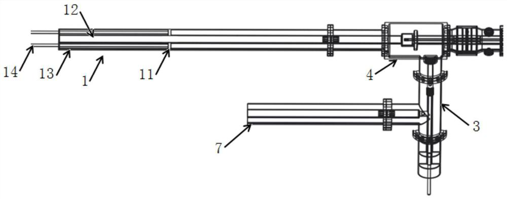
[0018] like figure 1 As shown, the standing wave resonance aging device of the high power input coupler provided by the present invention includes a first pullable short circuit 1 , a second pullable short circuit 2 and an adjustable secondary coupler 3 .

[0019] One end of the first pullable short-circuiter 1 is respectively connected to the non-vacuum end of the first high-power input coupler 5 and one end of the adjustable secondary co...


PUM


Abstract

The invention relates to a standing wave resonance seasoning device and method for a high-power input coupler, which is characterized in that it comprises a first pullable short circuiter, a second pullable short circuiter and an adjustable secondary coupler; the first pullable short circuit Connect the non-vacuum end of the first high-power input coupler and the adjustable secondary coupler, connect the vacuum end of the first high-power input coupler to the vacuum end of the second high-power input coupler, and connect the non-vacuum end of the second high-power input coupler The second pullable short-circuiter is fixedly connected, and the adjustable secondary coupler is also fixedly connected to the radio frequency power source; the first pullable short-circuiter and the second pullable short-circuiter are slidingly connected with a metal short-circuit board, and the gap between the two metal short-circuit boards is The distance is an integral multiple of the half-wavelength of the electromagnetic field. The first pullable short circuit, the second pullable short circuit, the first high-power input coupler, the second high-power input coupler and the two metal short-circuit plates form a movable coaxial The standing wave resonant cavity can be used in the field of accelerators.

Description

technical field [0001] The invention relates to a standing wave resonance aging device and method for a high-power input coupler, belonging to the field of accelerators. Background technique [0002] In the field of accelerators, coaxial high power input couplers are commonly used to provide energy from an RF power source to an RF accelerating cavity. Before the high-power input coupler is formally installed in the RF cavity, it needs to be experienced offline to improve the actual operation stability. The common offline aging methods of couplers are traveling wave aging and standing wave aging. In order to reduce the power required by the offline aging method, a traveling wave resonant ring device is usually used, but the structure of the device is complex and the power gain is low. The gain is generally only It is about 20 times. In recent years, researchers at Fermilab in the United States have proposed a standing wave partial resonance device, which contains a total re...

Claims


Application Information

Patent Timeline
Patent Type & Authority Patents(China)
IPC IPC(8): G01D21/02H01P11/00
CPCG01D21/02H01P11/00
Inventor 林泽强蒋天才吴安东何源
Owner INST OF MODERN PHYSICS CHINESE ACADEMY OF SCI
Learn More