Constant-current constant-voltage induction type wireless charging system based on variable secondary structure

A technology of wireless charging, constant current and constant voltage, applied in the direction of current collectors, electric vehicles, electrical components, etc., can solve the problems of increasing the power capacity of the inverter, high harmonic content of the output current of the inverter, and low efficiency

CN112366777AActive Publication Date: 2021-02-12INST OF ELECTRICAL ENG CHINESE ACAD OF SCI +1
8 Cites 3 Cited by

Patent Information

Authority / Receiving Office
CN · China
Current Assignee / Owner
Publication Date
2021-02-12

Smart Images

  • Figure 1
    Figure 1
  • Figure 2
    Figure 2
  • Figure 3
    Figure 3
Patent Text Reader

Abstract

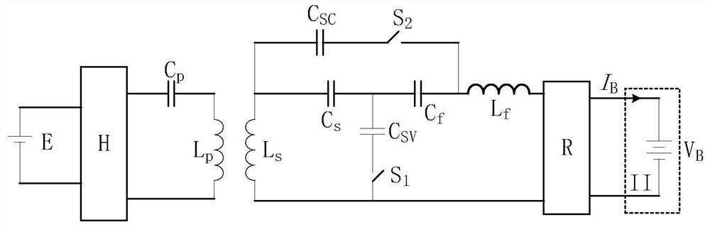
The invention discloses a constant-current constant-voltage induction type wireless charging system based on a variable secondary structure. In a receiving part of the system, a receiving coil Ls is sequentially connected with a compensation capacitor Cs, a compensation capacitor Cf, a compensation inductor Lf and a rectifier filter R in series; one end of the constant voltage compensation capacitor CSV, connected in series with a first change-over switch S1, is connected with a common point of the compensation capacitor Cs and the compensation capacitor Cf; and the other end of the constant voltage compensation capacitor CSV, connected in series with the first change-over switch S1, is connected with a common point of the receiving coil Ls and the rectifier filter R; one end of the constant-current compensation capacitor CSC, connected in series with a second change-over switch S2, is connected with a common point of the compensation capacitor Cs and the receiving coil Ls; the other end of the constant-current compensation capacitor CSC, connected in series with the second change-over switch S2, is connected with a common point of the compensation inductor Lf and the compensationcapacitor Cf. Constant-voltage and constant-current output of the system is achieved by controlling the states of the first change-over switch S1 and the first change-over switch S2.
Need to check novelty before this filing date? Find Prior Art

Description

technical field

[0001] The invention relates to an inductive wireless charging system. Background technique

[0002] Inductive wireless power transfer technology is a new power supply method that transfers electrical energy to the load in a non-contact manner through the principle of electromagnetic induction. The non-contact charging technology of electric vehicles is gradually favored by enterprises and consumers due to its convenience, speed and safety. This technology can strengthen the competitiveness of electric vehicles compared with traditional fossil energy vehicles and promote the development of the electric vehicle industry. application and development prospects.

[0003] In order to prolong the service life and charging times of the on-board battery and improve the safety of the charging system, the charging process of the battery is mainly divided into two charging modes: constant current and constant voltage: in the initial stage of charging, it is the constan...

Examples

Embodiment Construction

[0101] Such as figure 1 As shown, the constant current constant voltage inductive wireless charging system based on variable secondary structure of the present invention is composed of a transmitting part and a receiving part; the transmitting part includes a DC power supply E, a high frequency inverter H, and a primary compensation capacitor connected in series in sequence C p and the primary transmit coil L P ; The receiving part includes receiving coils L connected in series in sequence s , switching circuit I, compensation inductance L f , rectifier filter R and load II, characterized in that the receiving coil L s with compensation capacitor C s , compensation capacitor C f , compensation inductance L f And the rectifier filter R is connected in series in turn; the constant current compensation capacitor C SC with the first toggle switch S 1 One end after series connection with compensation capacitor C s and compensation capacitor C f The common point is connect...