Directional guide mechanism, device, method and medium

A guide column, thickness direction technology, applied in brake actuators, devices for preventing/restricting/restoring the movement of parts of control mechanisms, mechanical control devices, etc. problems, to achieve the effect of a wide range of applications and high operating accuracy

Pending Publication Date: 2019-11-22
杨斌堂
View PDF6 Cites 0 Cited by
  • Summary
  • Abstract
  • Description
  • Claims
  • Application Information

AI Technical Summary

Problems solved by technology

[0003] However, the spatial positioning and pointing systems proposed in these patent applications are based on complex components, especially optical systems, which are costly, complex in composition, and difficult to miniaturize

Method used


Image

  • Directional guide mechanism, device, method and medium
  • Directional guide mechanism, device, method and medium
  • Directional guide mechanism, device, method and medium

Examples


Embodiment 1

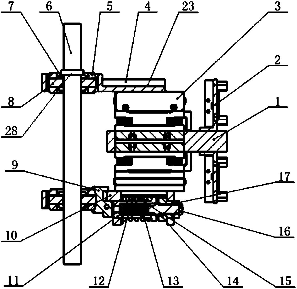
[0137] Such as Figure 5 As shown, the number of mobile unit assemblies 900 is one; the second mobile unit 902 is relatively fixed to the housing of the locking mechanism, for example, they are all fastened on the same rigid bracket, and for example, the second mobile unit 902 passes through The rigid bracket is firmly connected with the housing of the locking mechanism.

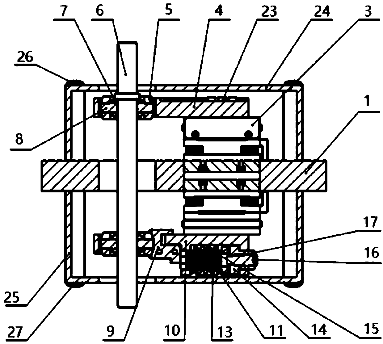
[0138] The locking mechanism includes a pair of clamping mechanisms 904 ; wherein, the wide ends 90411 are arranged oppositely between two clamping mechanisms 904 in the pair of clamping mechanisms 904 . In a variation example, the narrow ends 90412 of the paired clamping mechanisms 904 are arranged opposite to each other, for example, Image 6 shown.

[0139] Specifically, such as Figure 10 As shown, the locking mechanism includes a clamping mechanism 904; the clamping mechanism 904 includes a clamping chamber 9041, a clamping clip 9042, and a clip driver 9043;

[0140] The width of the clamping chambe...

Embodiment 2

[0156] Such as Image 6 shown, for Figure 5 change example. In this variation example, the narrow ends 90412 of the two clamping mechanisms 904 in the paired clamping mechanisms 904 are arranged opposite to each other.

[0157] exist Image 6 middle:

[0158] - To allow the first mobile unit 901 to slide freely to the left and right relative to the second mobile unit 902, the clamp clips 9042 in the left and right clamp mechanisms 904 are located at the wide end 90411 and the wide end 90411 respectively;

[0159] - To allow the first mobile unit 901 to slide freely to the left relative to the second mobile unit 902, the clamping parts 9042 in the left and right clamping mechanisms 904 are respectively located at the narrow end 90412 and the wide end 90411;

[0160] - To allow the first mobile unit 901 to slide freely to the right only relative to the second mobile unit 902, the clamp clips 9042 in the left and right clamp mechanisms 904 are respectively located at the wid...

Embodiment 3

[0163] Such as Figure 7 shown, for Figure 5 change example. In this variation example, two clamping mechanisms 904 in the pair of clamping mechanisms 904 are located on the same side of the first moving unit 901 .

[0164] exist Image 6 In a modified example, two clamping mechanisms 904 in the pair of clamping mechanisms 904 may also be located on the same side of the first moving unit 901 .


PUM


Abstract

The invention provides a directional guide mechanism, a device, a method and a medium. The directional guide mechanism comprises a swing ring structure, a displacement structure and a substrate (1), the swing ring structure is arranged on the displacement structure; the displacement structure is arranged on the substrate (1); the displacement structure is arranged at one end of the substrate (1) in the thickness direction, or displacement structures are arranged at the two ends of the substrate (1) in the thickness direction. The swing ring structure is provided with a rotation stopping mechanism, and the rotation stopping mechanism can lock or unlock movement of the corresponding swing ring structures. And / or the displacement structure is provided with a locking mechanism, and the lockingmechanism can lock or unlock the movement of the corresponding displacement structure. The directional guide mechanism, the device, the method and the medium can achieve the pointing of any point ofthe shaft structure in a specific spatial range, are suitable for various devices in the fields of orientation, positioning processing and spatial positioning pointing, and are wide in application range and high in operation precision.

Description

technical field [0001] The present invention relates to the fields of orientation, positioning processing and spatial positioning and pointing, and in particular relates to an orientation guiding mechanism, equipment, method and medium. Background technique [0002] Spatial positioning has a wide range of applications in industrial automation, aerospace, biomedical and other fields. Existing space positioning and pointing systems, such as the inertial pointing control method and control system of the arm-type space astronomical telescope provided by the patent document CN104483899A, utilize multiple inertial sensors and servo motors to realize the positioning and pointing of the telescope on the basis of a dynamic model; The optical pointing system provided by document CN103970262A utilizes an image sensor and a reference light source to realize spatial pointing. [0003] However, the spatial positioning and pointing systems proposed in these patent applications are based o...

Claims


Application Information

Patent Timeline
Patent Type & Authority Applications(China)
IPC IPC(8): G05G5/02
CPCF16D65/14G05G5/02
Inventor 杨斌堂
Owner 杨斌堂
Why Eureka
Try Eureka