Eureka AIR delivers breakthrough ideas for toughest innovation challenges, trusted by R&D personnel around the world.

Grating groove bending automatic control and correcting method

A correction method, grating engraving technology, applied in the direction of diffraction grating, metal processing, etc., can solve the problems of poor correction effect of reticle bending, low efficiency, complicated design process, etc., to reduce grating reticle bending, improve quality, and improve operation Effects on precision and productivity

Active Publication Date: 2014-12-24
CHANGCHUN INST OF OPTICS FINE MECHANICS & PHYSICS CHINESE ACAD OF SCI
View PDF3 Cites 12 Cited by
  • Summary
  • Abstract
  • Description
  • Claims
  • Application Information

AI Technical Summary

Problems solved by technology

[0004] The present invention solves the problems that the existing correction method of grating ruled line bending adopts repeated improvement design and installation and debugging of the mechanical structure of the grating ruled machine, and there are problems such as complicated design process, low efficiency and poor effect of ruled line bending correction. Provide an automatic control and correction method for grating rule line bending

Method used


Image

  • Grating groove bending automatic control and correcting method
  • Grating groove bending automatic control and correcting method
  • Grating groove bending automatic control and correcting method

Examples


Embodiment Construction

[0032] The present invention will be described in further detail below in conjunction with the accompanying drawings and specific embodiments.

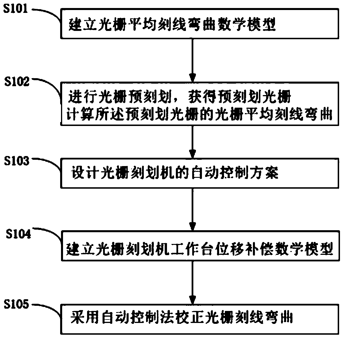
[0033] see figure 1 , the present embodiment provides a method for automatically controlling and correcting grating reticle curvature, which includes the following steps:

[0034] S101. Establish a mathematical model of grating mean line curvature.

[0035] Further includes:

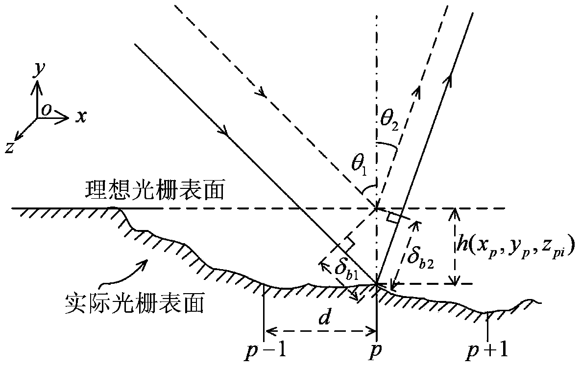
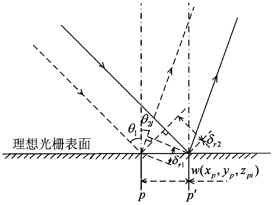
[0036] S1011. Deriving mathematical expressions between grating line errors, grating base surface shape errors, and grating diffraction wavefronts under grating cone diffraction.

[0037] S1012. Deleting the grating swing angle and the overall position error of the grating rule from the grating rule error to obtain a relational expression between the grating average rule bend and the grating rule error.

[0038] Specifically, in this embodiment, the geometrical optics method is used to derive the relational expression between the grating rule error, the base ...


PUM


Abstract

The invention provides a grating groove bending automatic control and correcting method and relates to the technical field of grating ruling. The automatic control and correcting method solves the problems that improvement design and installation debugging need to be repeatedly carried out on the mechanical structure of a grating ruling machine in a mechanical design method in the existing grating groove bending correction technique, the design process is complex, efficiency is low and the groove bending correction effect is poor. The method includes the steps of (S101) building a grating average groove bending mathematical model, (S102) conducting grating pre-ruling to obtain a pre-ruling grating, and calculating grating average groove bending of the pre-ruling grating, (S103) designing an automatic control scheme of the grating ruling machine, (S104) building a work table displacement compensation mathematical model of the grating ruling machine, and (S105) correcting grating groove bending in an automatic control method. By means of the grating groove bending automatic control and correcting method, grating groove bending can be effectively reduced, grating diffraction wavefront quality is improved, and operation precision and work efficiency of the grating ruling machine are improved.

Description

technical field [0001] The invention relates to the technical field of grating scribing, in particular to an automatic control and correction method for grating scribe line bending that reduces the grating scribe line bending. Background technique [0002] Due to the influence of factors such as linearity error and limited rigidity of the diamond knife guide rail of the grating marking machine scoring system, the planar grating made by the mechanical scoring method can cause the diamond knife to run along the curved track, so that the mechanical marking of the grating occurs. Curved lines. The bending of the reticle means that the reticle of each reticle of the grating is curved, and when the performance of the marking system of the grating marking machine is stable, the bending shape and amplitude of each reticle of the grating are relatively repetitive. The bending error of the grating rule affects the quality of the grating diffraction wavefront. Changchun Institute of ...

Claims


Application Information

Patent Timeline
Patent Type & Authority Applications(China)
IPC IPC(8): G02B5/18B26D3/08
Inventor 李晓天于海利唐玉国杨超刘兆武齐向东
Owner CHANGCHUN INST OF OPTICS FINE MECHANICS & PHYSICS CHINESE ACAD OF SCI
Why Eureka
Eureka Blog
Learn More