Laser

A technology of lasers and laser sources, applied in the direction of lasers, laser components, phonon exciters, etc., can solve problems such as out-of-focus, affecting operation accuracy, affecting operation power and operation quality, and solve coaxial problems and improve operation Effects on precision and quality of work

Pending Publication Date: 2019-11-22
ZHUHAI GUANGKU TECH CO LTD
View PDF0 Cites 0 Cited by
  • Summary
  • Abstract
  • Description
  • Claims
  • Application Information

AI Technical Summary

Problems solved by technology

[0004] refer to figure 2 , due to the problem of dispersion in the crystal material of the isolator 12, there is generally a misalignment problem between the 650nm indicating red light output from the isolator and the 1064nm laser, so that the working position of the laser and the marking position of the red light do not overlap, which affects the operation Precision, and because the refractive index of light of different wavelengths is different when passing through optical devices of different materials, there is a problem of different focus after passing through the isolator and optical lens assembly, which in turn causes the laser to fail to focus on the working position of the target , affecting the work efficiency and work quality

Method used


Image

  • Laser
  • Laser
  • Laser

Examples


Embodiment Construction

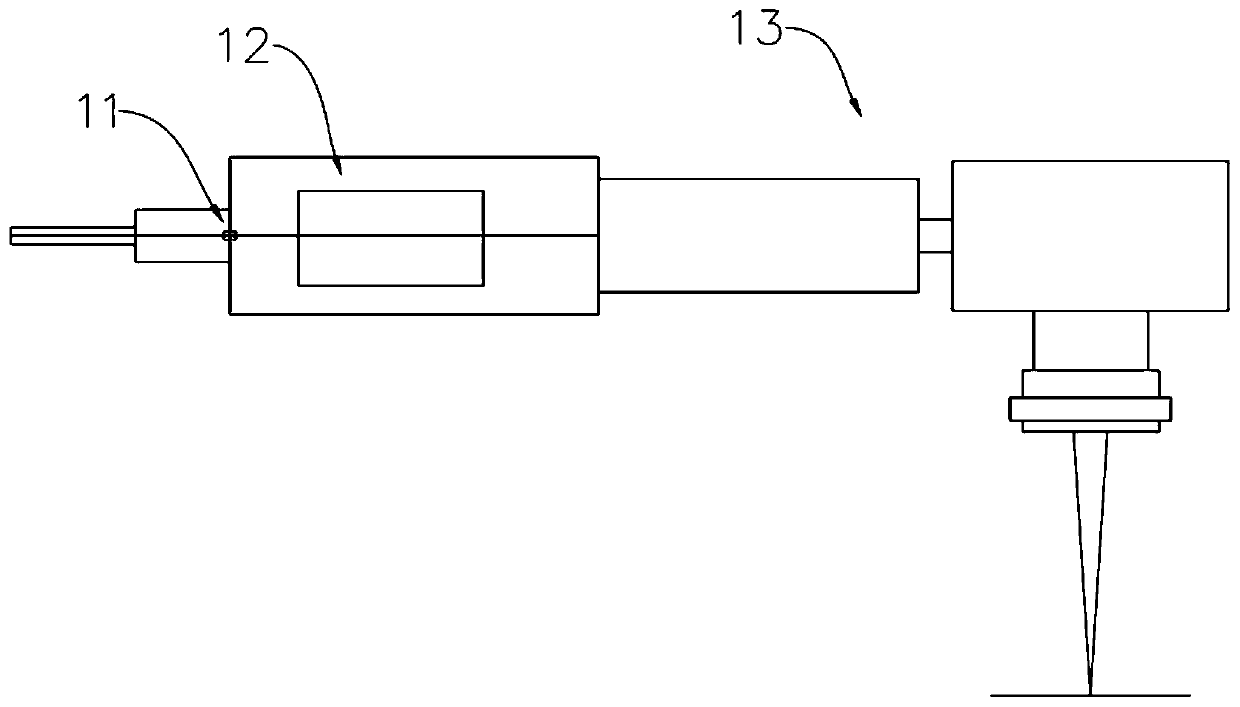
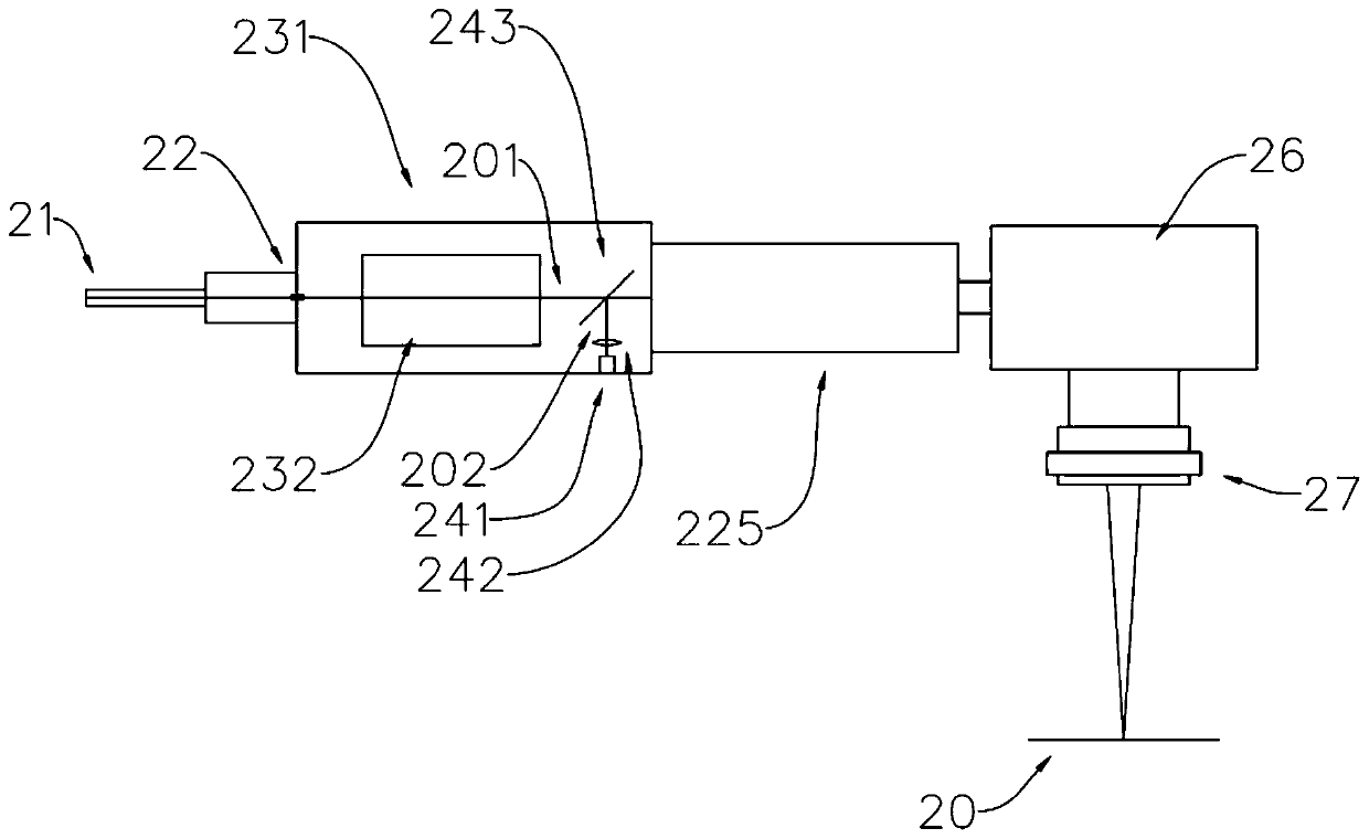
[0027] refer to image 3 and Figure 4 , the laser is sequentially provided with a laser source (not shown), a collimator 22, an isolator 232 and an optical lens assembly along the output main optical path, the laser source is connected with the collimator 22 through an optical fiber 21, and the output collimation The laser, in this embodiment the laser uses the laser 201 with a wavelength λ1 of 1064nm, which is invisible light. The optical lens assembly includes a beam expander 225, a vibrating mirror 26 and a field lens 27 arranged in sequence along the output main optical path, the beam expander 225 is located at the rear stage of the dichromatic sheet 243, the vibrating mirror 26 is located at the rear stage of the beam expander 225, and the field lens 27 is located at the rear stage of the vibrating mirror 26 . The laser output from the laser source passes through the collimator 22 , the isolator 232 , the beam expander 225 , the vibrating mirror 26 and the field lens 2...


PUM


Abstract

The invention provides a laser. A laser source, a collimator, an isolator and an optical lens assembly are sequentially arranged along the output main light path. Laser output by the laser source sequentially penetrates through the collimator, the isolator and the optical lens assembly. The laser further comprises a double-color sheet, an indication light source and an indication light lens. The double-color sheet is arranged on the output main light path and is positioned between the isolator and the optical lens assembly; laser is transmitted and input into the optical lens assembly from thedouble-color sheet, the indication light source, the indication light lens and the double-color piece are sequentially arranged along an indication light path, indication light output by the indication light source passes through the indication light lens and then is input into the double-color piece, and the indication light is reflected and input into the optical lens assembly from the double-color piece. According to the scheme, the laser and the indication light can be coaxially combined in the output main light path to be transmitted, in addition, the color difference between the laser and the indication light is compensated by adjusting the indication light lens, then coaxial and confocal output of the indication light and the laser is achieved, and therefore the operation precisionand the operation quality of cutting or welding and the like are effectively improved.

Description

technical field [0001] The invention relates to the field of optical devices, in particular to a laser. Background technique [0002] In the fiber laser marking, cutting and welding systems, since the 1064nm laser is invisible light, the visible light 650nm red light is often used as the indicating light path, so as to realize the positioning operation. The indicator light of fiber laser marking is usually coupled into the optical fiber through the WDM of the laser system, and the signal laser and indicator light are output from the beam expander of the isolator, and then focused by the galvanometer and the field lens. [0003] refer to figure 1 , figure 1 It is a schematic diagram of the optical path of an existing laser. The laser is provided with a collimator 11, an isolator 12 and an optical lens assembly 13 along the optical path. Through the collimator 11, the parallel light λ1 can output laser light of 1064nm and λ2 red light of 650nm. Position the working position...

Claims


Application Information

Patent Timeline
IPC IPC(8): H01S3/00B23K26/06
CPCB23K26/0648H01S3/0064H01S3/0071
Inventor 黄汉凯张大鹏邓剑钦肖新亮叶松邓耀辉
Owner ZHUHAI GUANGKU TECH CO LTD
Why Eureka
Try Eureka