Double-rotor generator and control method thereof

A generator and double-rotor technology, applied to control the direction of generators, synchronous machines, electrical components, etc. through changes in the magnetic field, can solve the problems of three-phase asynchronous generator power factor lag, etc., to improve operating efficiency, reduce vibration and noise , Enhance the effect of the air gap magnetic field

Active Publication Date: 2019-11-22
QILU UNIV OF TECH
View PDF30 Cites 4 Cited by
  • Summary
  • Abstract
  • Description
  • Claims
  • Application Information

AI Technical Summary

Problems solved by technology

However, the power factor of the three-phase asynchronous generator lags behind, so that more reactive power needs to be obtained from the grid, and when the generator is under light load, the power factor is low so that it consumes a considerable amount of electric energy

Method used


Image

  • Double-rotor generator and control method thereof
  • Double-rotor generator and control method thereof
  • Double-rotor generator and control method thereof

Examples


Embodiment 1

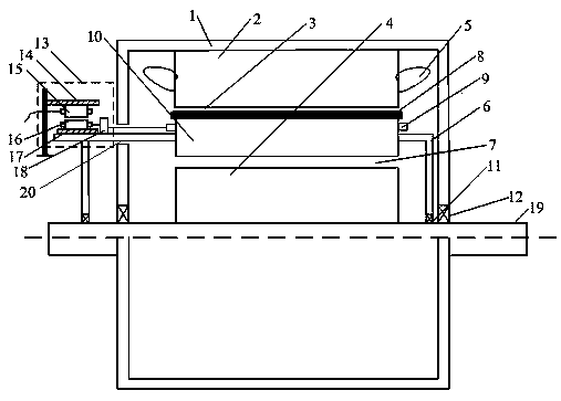
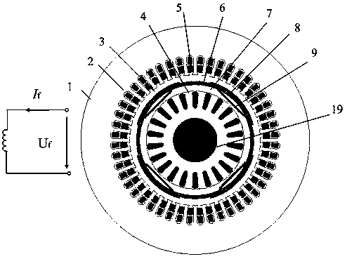
[0029] like figure 1 and figure 2 As shown, a dual-rotor generator includes a casing 1, the casing 1 is rotatably connected to a rotating shaft 19, and a stator is fixedly connected inside the casing 1, and the stator includes a stator core 2 and a stator winding 5, The stator core 2 is fixed on the casing 1, the stator winding 5 is installed in the slot of the stator core 2, the stator winding 5 is a three-phase symmetrical AC winding, and the rotating shaft 19 is fixedly connected with an inner squirrel cage The rotor 4, the inner squirrel-cage rotor 4 includes the inner squirrel-cage rotor iron core and the rotor squirrel-cage bars, the inner squirrel-cage rotor 4 is fixedly connected with the rotating shaft 19, the stator and the inner squirrel-cage rotor 4 An outer permanent magnet rotor 10 is arranged between them, the stator is arranged on the outer side of the outer permanent magnet rotor 10, the outer permanent magnet rotor 10 is rotationally connected with the rota...

Embodiment 2

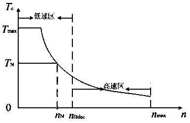
[0038] According to the characteristics and operating characteristics of the dual-rotor generator, its operating area is divided into two parts, the low-speed area and the high-speed area, such as image 3 shown.

[0039] In the low-speed area, the field-increasing control is usually used, and in the high-speed area, the field-weakening control is usually used. The operation control of the drive system can adopt the following magnetization control or field weakening control:

[0040] Magnetization control: The external permanent magnet rotor excitation winding 9 is magnetized to provide large torque and improve the short-term overload capacity of the generator. The torque detection device is used to collect real-time torque information. When the load torque is less than or equal to the generator When the rated torque is , the magnetization control is not required, that is to say, the excitation current in the field winding 9 of the outer permanent magnet rotor is I f =0; wh...


PUM


Abstract

A double-rotor generator includes a machine shell that is rotationally connected with a rotating shaft. A stator is fixedly connected into the machine shell, wherein the rotating shaft is fixedly connected with an inner squirrel-cage rotor, an outer permanent magnet rotor is arranged between the stator and the inner squirrel-cage rotor, the outer permanent magnet rotor is rotatably connected withthe rotating shaft, an outer air gap is arranged between the outer permanent magnet rotor and the stator, and an inner air gap is arranged between the inner squirrel-cage rotor and the outer permanentmagnet rotor. The outer permanent magnet rotor is added in a traditional squirrel-cage induction generator. The outer permanent magnet rotor provides adjustable excitation; therefore, an operating power factor and power density of the generator are improved, the rotating speed of the generator can be adjusted within a wide range, the outer permanent magnet rotor can rotate freely, the rotating speed of the outer permanent magnet rotor and a synchronous rotating magnetic field generated by a stator winding are overlapped, and the current of the stator winding of the generator is reduced.

Description

technical field [0001] The invention relates to the technical field of generators, in particular to a dual-rotor generator and a control method thereof. Background technique [0002] Three-phase asynchronous generators are widely used in the field of industrial and agricultural production due to their advantages of simple structure, durability and less maintenance. However, the power factor of the three-phase asynchronous generator lags behind, so more reactive power needs to be obtained from the grid. In addition, when the generator is under light load, the power factor is low so that it consumes a considerable amount of electric energy. With the increasing awareness of energy saving, emission reduction and environmental protection, it is becoming more and more urgent to improve the efficiency of three-phase asynchronous generators. This is the weak point of prior art. Contents of the invention [0003] The technical problem to be solved by the present invention is to p...

Claims


Application Information

Patent Timeline
Patent Type & Authority Applications(China)
IPC IPC(8): H02K16/02H02K21/46H02P9/14
CPCH02K16/02H02K21/46H02P9/14
Inventor 刁统山刘加和王艳
Owner QILU UNIV OF TECH
Why Eureka
Try Eureka