Heat exchanger of refrigerator

A technology of heat exchangers and heat exchange parts, which is applied in the direction of heat exchange equipment, indirect heat exchangers, heat exchanger types, etc., can solve the problems of reduced heat exchange volume, low heat exchange efficiency, small heat exchange volume, etc., and achieve Effect of improving heat exchange efficiency and heat exchange amount

Inactive Publication Date: 2019-11-22
LG ELECTRONICS INC
View PDF3 Cites 0 Cited by
  • Summary
  • Abstract
  • Description
  • Claims
  • Application Information

AI Technical Summary

Problems solved by technology

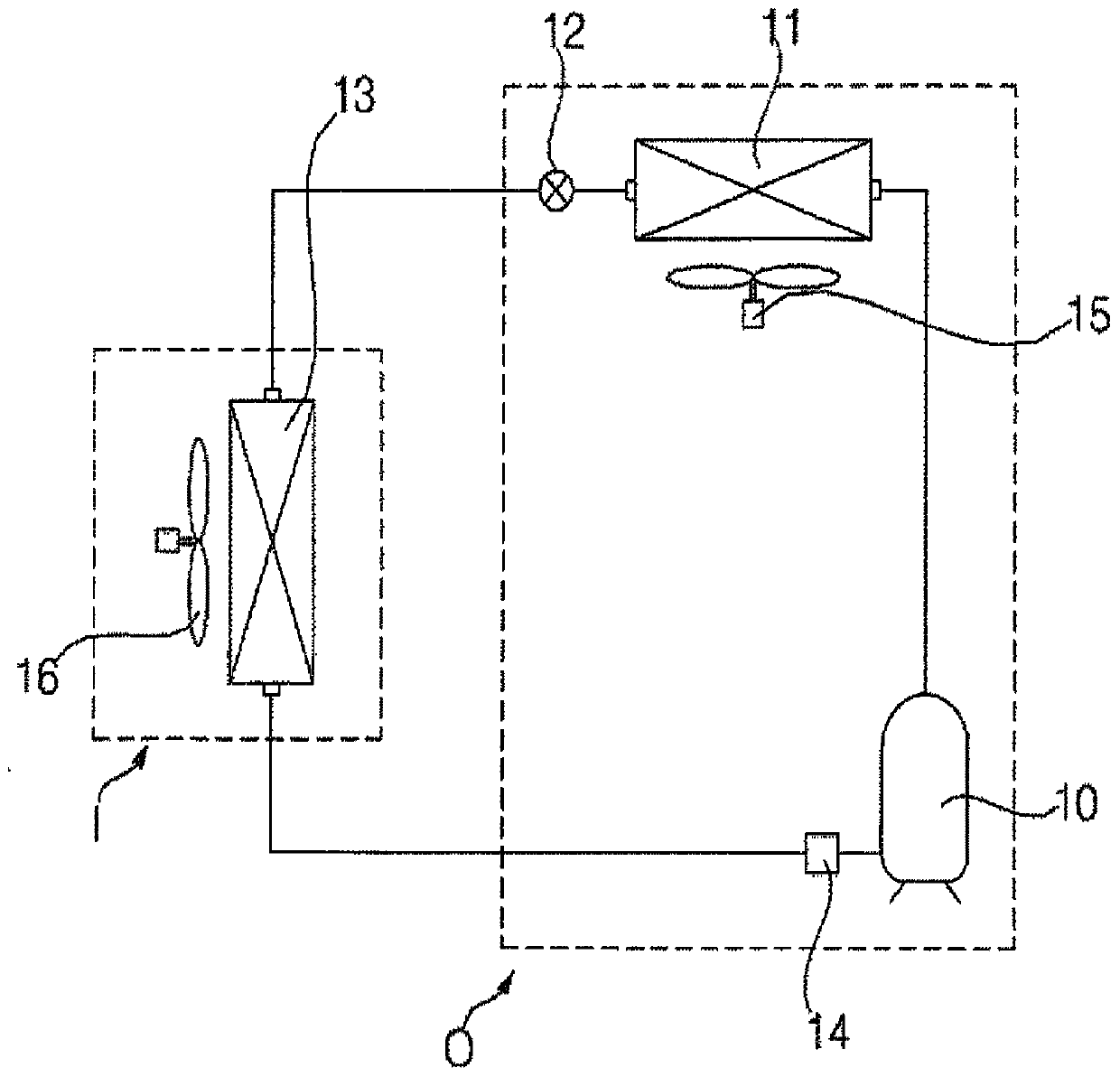
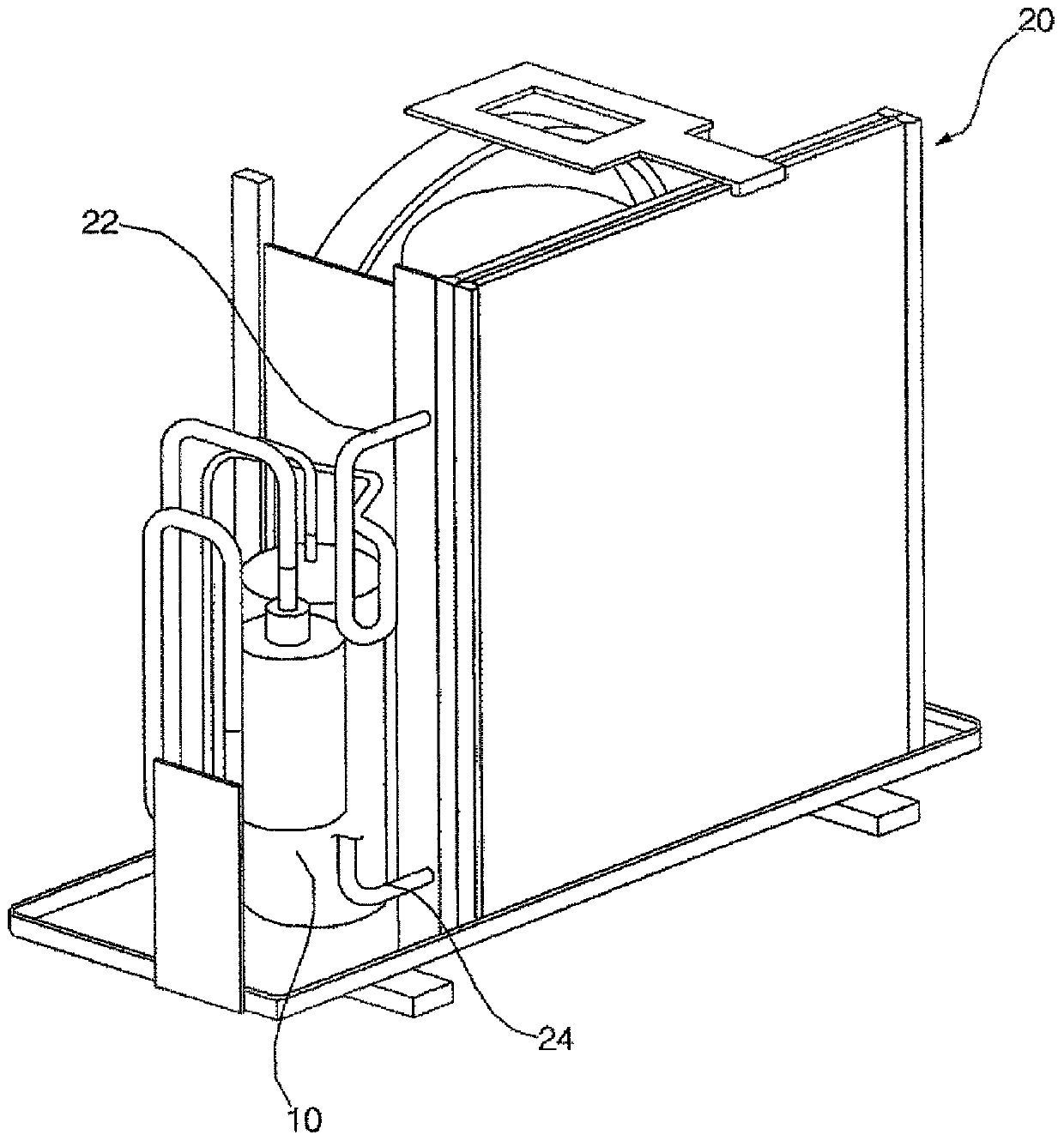
[0007] Since the small micro-channel heat exchangers used in existing refrigerators are produced in a one-turn system, only a single refrigerant channel can be designed, and the heat exchange efficiency is low.
In addition, in a small-sized micro-channel heat exchanger used in a refrigerator, etc., the number of refrigerant tubes at the inlet and outlet is arranged to be the same, so the temperature difference between the refrigerant and the air is large at the part where the high-temperature refrigerant flows, so that although the heat The exchange volume is large but the heat exchange efficiency is low, and the temperature difference between the refrigerant and the air is small at the place where the low-temperature refrigerant flows out, so although the heat exchange volume is small, the heat exchange efficiency is high, and thus, there is a disadvantage that the overall heat exchange efficiency decreases
[0008] In addition, in the conventional heat exchanger, the cross-sectional area of ​​the refrigerant tube at the point where the refrigerant flows in is the same as that at the point where the refrigerant flows out, so the change in the specific volume of the refrigerant cannot be taken into account, resulting in a problem that the amount of heat exchange decreases.

Method used


Image

  • Heat exchanger of refrigerator
  • Heat exchanger of refrigerator
  • Heat exchanger of refrigerator

Examples


Embodiment Construction

[0034] By describing the embodiments in detail below with reference to the accompanying drawings, the advantages, features and implementation methods of the present invention will be more clearly understood. However, the present invention is not limited to the embodiments disclosed below, and can be embodied in various shapes that are different from each other. , the protection scope of the present invention is determined only by the scope of the claims. Throughout the specification, the same reference numerals refer to the same constituent elements.

[0035] As shown in the figure, relative terms such as "below", "beneath", "lower" and "lower" may be used as spatial relative terms in order to easily describe the relationship between one component and other components. On (above)", "upper (upper)" and so on. The relative terms of space should be understood as terms including not only the directions shown in the drawings but also the directions different from each other of th...


PUM


Abstract

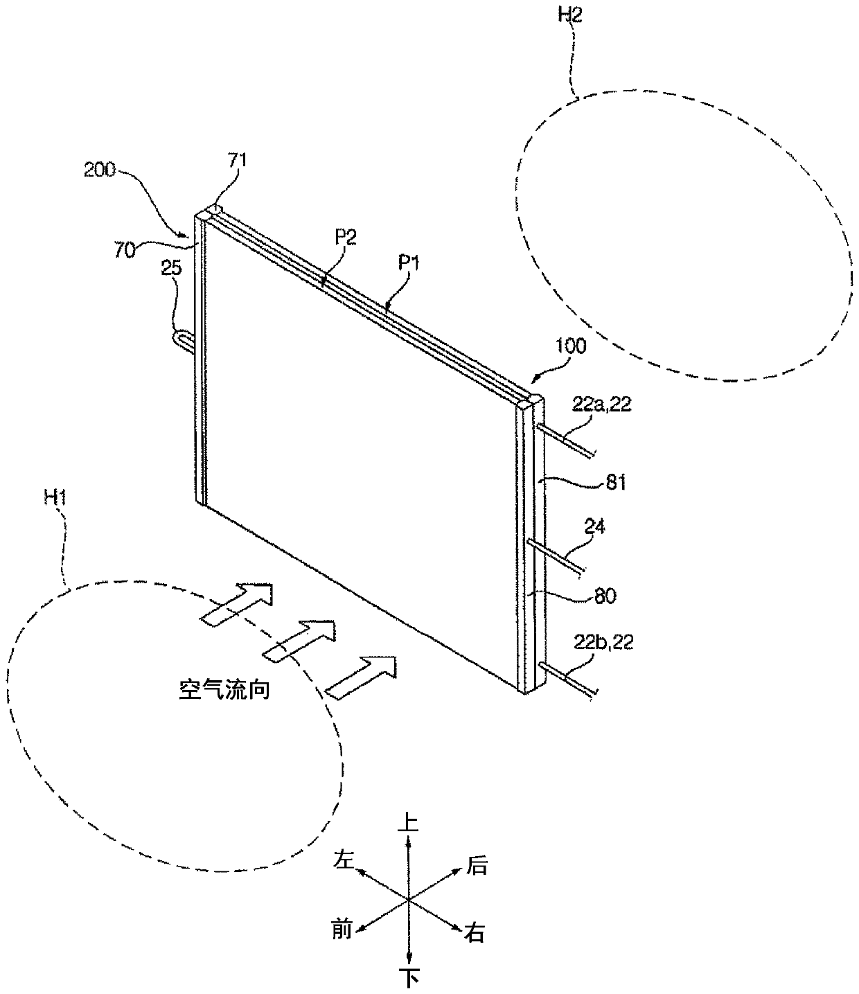
A heat exchanger of a refrigerator according to the present invention is a micro-channel type heat exchanger of a refrigerator comprising: a first heat exchanging unit including a plurality of flat tubes for exchanging heat between a refrigerant and air and connected to an inlet pipe through which the refrigerant flows; a second heat exchanging unit including a plurality of flat tubes for exchanging heat between the refrigerant and air, disposed on the outside of the first heat exchanging unit and connected to a discharge tube through which the refrigerant is discharged; and a connection pipefor connecting the first heat exchanging unit and the second heat exchanging unit and supplying the refrigerant discharged from the first heat exchanging unit to the second heat exchanging unit, wherein the first heat exchanging unit is arranged to exchange heat with air that has been heat-exchanged with the second heat exchanging unit, and the sum of the cross sectional areas of the flat tubes ofthe first heat exchanging unit is larger than the sum of the cross sectional areas of the flat tubes of the second heat exchanging unit.

Description

technical field [0001] The present invention relates to a heat exchanger for a refrigerator. Background technique [0002] Generally, a heat exchanger can be used as a condenser or an evaporator in a refrigeration cycle device composed of a compressor, a condenser, an expansion mechanism, and an evaporator. [0003] In addition, the heat exchanger is installed in a vehicle, a refrigerator, or the like, and exchanges heat between the refrigerant and the air. [0004] Heat exchangers can be divided into finned tube heat exchangers, microchannel heat exchangers, etc. according to their structure. [0005] The finned tube heat exchanger is made of copper, and the microchannel heat exchanger is made of aluminum. [0006] Since the fine flow paths are formed inside the microchannel heat exchanger, it has an advantage of higher efficiency than the finned tube heat exchanger. [0007] Since the small micro-channel heat exchangers used in conventional refrigerators are produced in...

Claims


Application Information

Patent Timeline
Patent Type & Authority Applications(China)
IPC IPC(8): F28D1/053F25B39/04F28F1/12F25D19/00F28F3/04F28D21/00
CPCF25B39/04F28D1/0417F28D1/0435F28D1/05375F28D1/05383F28D2021/0068F28F1/126F28F1/24F28F2210/08F25B2339/043F25D19/00F28D2021/0063F28F3/048F28F2260/02F28D1/05391F28F1/128F28F9/02
Inventor 朴泰均金周赫李应烈崔智源
Owner LG ELECTRONICS INC
Why Eureka
Try Eureka