
Annular mechanical welding device

A mechanical welding and circular technology, which is applied in the direction of auxiliary devices, welding equipment, auxiliary welding equipment, etc., can solve the problems of reducing welding efficiency, increasing the construction cost of welding line, and not covering the welding work of workpieces to be welded well. The effect of high flexibility and efficiency improvement

Inactive Publication Date: 2019-11-26
凌军
View PDF7 Cites 2 Cited by
  • Summary
  • Abstract
  • Description
  • Claims
  • Application Information

AI Technical Summary

Problems solved by technology

[0002] Mechanical welding is a common process in the field of mechanical processing. Traditional mechanical welding uses linear operations, which cannot cover the welding operations on different sides of the workpiece to be welded well. It is necessary to set up multiple robotic arms for welding, which increases the construction cost of the welding line. Reduced welding efficiency, the application provides a ring welding device capable of continuous ring welding operations

Method used


Image

  • Annular mechanical welding device
  • Annular mechanical welding device
  • Annular mechanical welding device

Examples


Embodiment 1

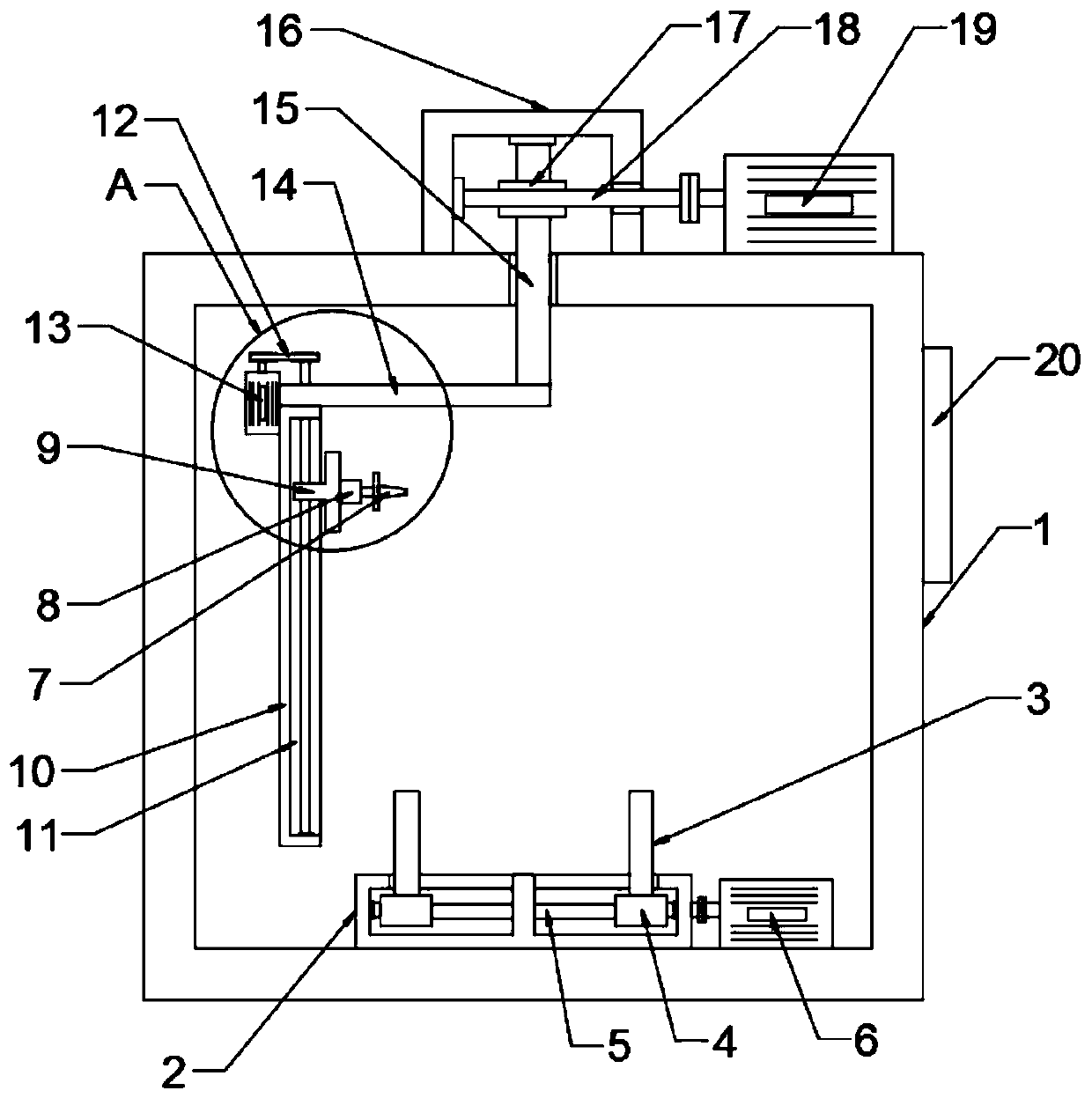
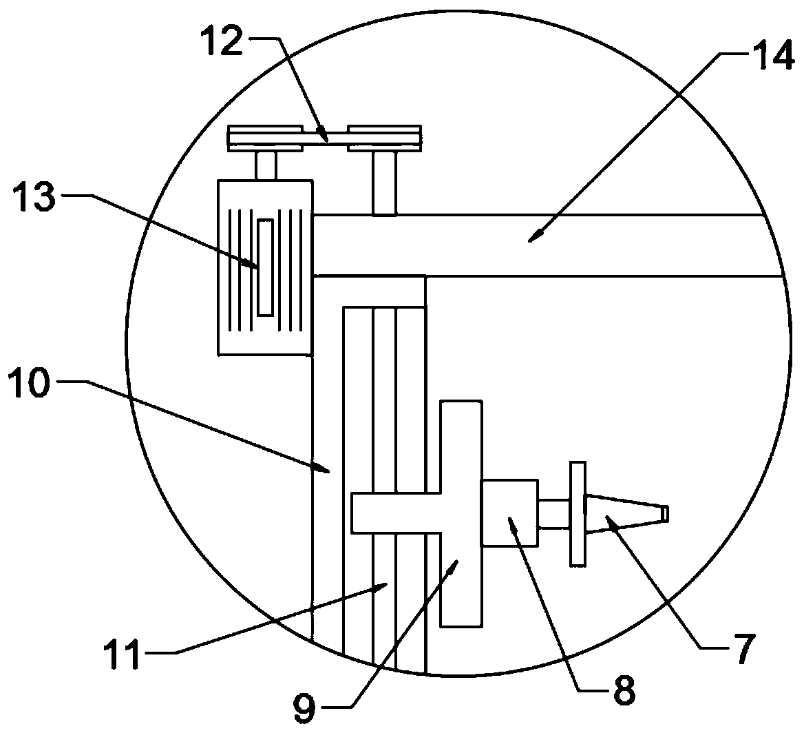
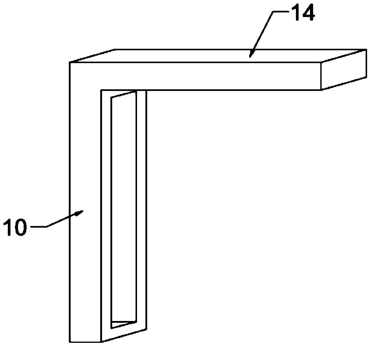
[0019] see Figure 1-3 , in an embodiment of the present invention, a ring-shaped mechanical welding device includes a box body 1; a welding torch 7 is arranged in the box body 1, and the welding torch 7 is connected to an external electric welding machine through a wire; the welding torch 7 is fixedly connected to an electric telescopic rod 8. The electric telescopic rod 8 is fixedly connected with a lifting block 9, and the electric telescopic rod 8 is used to adjust the horizontal position of the welding torch 7; the lifting block 9 is nested with a vertical plate 10, and the vertical plate 10 is provided with a vertical chute, The vertical chute is provided with a screw mandrel 11, the screw mandrel 11 runs through the lifting block 9 and is threadedly connected with the lifting block 9, the screw mandrel 11 extends to the top of the vertical plate 10 and is connected with a second screw mandrel motor 13 by a transmission belt 12, The second screw motor 13 is electrically ...

Embodiment 2

[0023] The difference between this embodiment and Embodiment 1 is that: a clamping seat 2 is provided below the welding torch 7, and a clamping plate 3 is arranged symmetrically above the clamping seat 2, and a moving block 4 is fixedly connected to the bottom of each clamping plate 3 , the moving block 4 is nested in the clamping seat 2, the clamping seat 2 is provided with a horizontal chute, the horizontal chute is provided with a two-way screw rod 5, and the two-way screw rod 5 runs through the moving block 4 and is threadedly connected with the moving block 4; The two-way screw 5 extends to the outside of the clamping seat 2 and is connected to the output shaft of the first screw motor 6 through a coupling. The first screw motor 6 is connected to the controller 20 through a wire. The first screw motor 6 Electrically connected with an external power supply, the first screw motor 6 drives the bidirectional screw 5 to rotate, and the bidirectional screw 5 drives the symmetric...


PUM


Abstract

The invention discloses an annular mechanical welding device. The annular mechanical welding device comprises a box body and a welding gun; the welding gun is fixedly connected with an electric telescopic rod; the electric telescopic rod is fixedly connected with a lifting block; the lifting block is embedded into a vertical plate; the upper end of the vertical plate is fixedly connected with a horizontal plate; the horizontal plate is fixedly connected with a rotating shaft; a worm wheel is fixed to and is connected with the rotating shaft in a sleeved manner; the worm wheel is engaged with aworm; and the worm is connected with a servo motor through a coupler. Through the vertical plate which is provided with a vertical sliding groove, a lead screw and the electric telescopic rod, the vertical height and the horizontal position of the welding gun are changed conveniently, so that position adjustment on different welding spots on the operation surface of one side is further adapted; and through the horizontal plate which is fixedly connected with the rotating shaft, the worm wheel, the worm and the servo motor, the circular motion of the welding gun is achieved, so that operationis further carried out on welding spots of different operation surfaces of a to-be-welded workpiece, the annular mechanical welding device has the relatively high flexibility, and the welding efficiency is improved.

Description

technical field [0001] The invention relates to the field of mechanical welding, in particular to an annular mechanical welding device. Background technique [0002] Mechanical welding is a common process in the field of mechanical processing. Traditional mechanical welding uses linear operations, which cannot cover the welding operations on different sides of the workpiece to be welded well. It is necessary to set up multiple robotic arms for welding, which increases the construction cost of the welding line. The efficiency of welding is reduced, and the present application provides a ring welding device capable of performing continuous ring welding operations. Contents of the invention [0003] The object of the present invention is to provide an annular mechanical welding device to solve the problems raised in the above-mentioned background technology. [0004] To achieve the above object, the present invention provides the following technical solutions: [0005] An a...

Claims


Application Information

Patent Timeline
Patent Type & Authority Applications(China)
IPC IPC(8): B23K37/02
CPCB23K37/0247B23K37/0252
Inventor 凌军
Owner 凌军
Learn More