
Feeding device for processing ball pin

A ball stud and equipment technology, applied in metal processing equipment, grinding/polishing equipment, manufacturing tools, etc., can solve problems such as low processing efficiency, high labor intensity, and reduce labor intensity of staff, so as to improve processing efficiency, The effect of reducing labor intensity

Active Publication Date: 2019-11-26
马鞍山市安工大智能装备技术研究院有限公司 +1
View PDF5 Cites 4 Cited by
  • Summary
  • Abstract
  • Description
  • Claims
  • Application Information

AI Technical Summary

Problems solved by technology

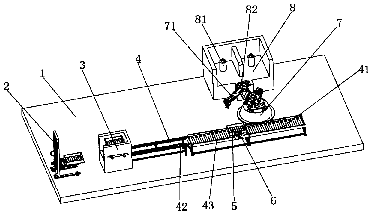
[0006] The present invention can realize fully automatic feeding and processing, loading and unloading of ball studs in the process of processing ball studs by setting a feeding forklift, a pallet warehouse, a first conveying frame, a second conveying frame, a pressing and positioning mechanism, and a pick-up robot. The fixed positioning during the feeding process avoids the cumbersome process of the staff manually placing the ball studs into the processing table for processing, liberates the hands of the staff and reduces the labor intensity of the staff. At the same time, the invention forms a complete The advanced feeding processing line greatly improves the processing efficiency of ball studs, so as to solve the problem that only ball studs are processed by manual feeding, and the labor intensity is too high and the processing efficiency is low. question

Method used


Image

  • Feeding device for processing ball pin
  • Feeding device for processing ball pin
  • Feeding device for processing ball pin

Examples


Embodiment Construction

[0030] The following will clearly and completely describe the technical solutions in the embodiments of the present invention with reference to the accompanying drawings in the embodiments of the present invention. Obviously, the described embodiments are only some, not all, embodiments of the present invention. Based on the embodiments of the present invention, all other embodiments obtained by persons of ordinary skill in the art without creative efforts fall within the protection scope of the present invention.

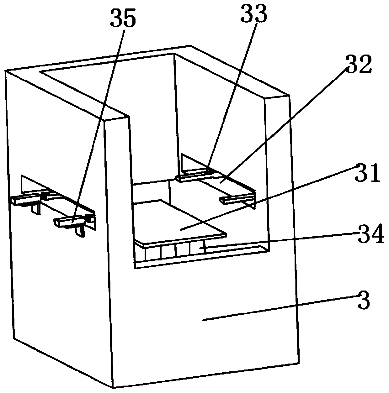
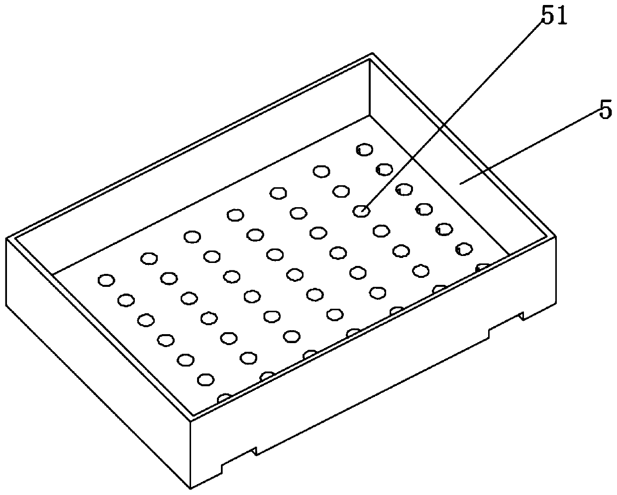
[0031] see Figure 1-6 As shown, this embodiment provides a feeding device for ball stud processing, including a workshop base 1, a first conveying frame 4, a second conveying frame 41, a loading forklift 2, a pick-up robot 7, and a processing table 8 and the pressing and positioning mechanism, the first conveying frame 4, the second conveying frame 41, the loading forklift 2, the picking robot 7 and the processing table 8 are all placed on the same horizontal plan...


PUM


Abstract

The invention discloses a feeding device for processing a ball pin. The feeding device for processing the ball pin comprises a workshop base, a first conveying rack, a second conveying rack, a feedingforklift, a pickup robot, a processing table and a pressing and positioning mechanism, wherein the first conveying rack, the second conveying rack, the feeding forklift, the pickup robot and the processing table are all arranged on the same horizontal plane, the processing table is positioned behind the pickup robot, the second conveying rack is positioned in front of the pickup robot, the pressing and positioning mechanism is positioned on the outer surface of the second conveying rack, the first conveying rack is positioned on the outer surface of one side of the second conveying rack, andthe outer surface of one side, far away from the second conveying rack, of the first conveying rack, is fixedly provided with a tray library. The feeding device for processing the ball pin can realizefull-automatic feeding in the ball pin processing process and positioning and fixing in the processing and feeding processes, the labor intensity of workers is reduced, and meanwhile, the feeding device for processing the ball pin forms a complete feeding processing line, and greatly improves the processing efficiency of the ball pin.

Description

technical field [0001] The invention relates to the field of ball stud feeding equipment, in particular to a feeding device for ball stud processing. Background technique [0002] Ball studs are widely used in independent suspension systems. Control arms or thrust rods are often connected to other components through ball studs at the end. There are two main types of structure: one is the combined type of ball pin and integral ball seat, and the other is the combined type of hemispherical ball pin and spherical member. Regardless of the structure of the ball pin, the ball head needs to be polished. Make it smooth to avoid friction and hinder rotation during use; [0003] However, during the grinding process of the existing ball stud pins, manual loading is often used for loading, or when using a machine for loading, it cannot be automatically positioned and fixed, and manual positioning and fixing is still required, which greatly increases the work of the staff. Labor inten...

Claims


Application Information

Patent Timeline
IPC IPC(8): B24B41/00B24B41/06
CPCB24B41/005B24B41/067
Inventor 王璐解安东舒军勇
Owner 马鞍山市安工大智能装备技术研究院有限公司
Learn More