Spiral wave electromagnetic acceleration plasma source

A plasma source and helical wave technology, which is applied in the directions of plasma, plasma, ion beam tube, etc., can solve the problems of restricting the life of the thruster, low acceleration efficiency, and large acceleration area, and achieves the realization of thrust controllability, The effect of eliminating electrode corrosion and improving diversity

Active Publication Date: 2019-11-26
BEIHANG UNIV
View PDF7 Cites 14 Cited by
  • Summary
  • Abstract
  • Description
  • Claims
  • Application Information

AI Technical Summary

Problems solved by technology

The helical wave ion thruster uses the electrostatic grid acceleration method to accelerate ions, its acceleration efficiency is low, the required acceleration area is large, the alignment of the mu

Method used


Image

  • Spiral wave electromagnetic acceleration plasma source

Examples


Embodiment Construction

[0030] The present invention will be further described below in conjunction with the accompanying drawings and embodiments. It should be understood that the following embodiments are intended to facilitate the understanding of the present invention, and have no limiting effect on it.

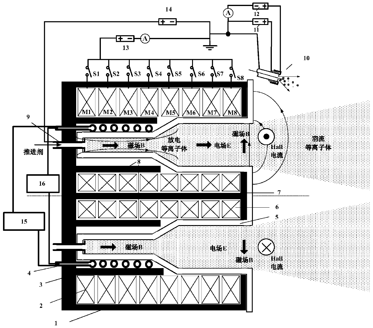
[0031] Such as figure 1 As shown, the helicon wave electromagnetic accelerated plasma source of the present invention has a cylindrical shape as a whole, and sequentially includes an outer magnetic shield 1, an outer magnetic coil group 2, an inner magnetic shield 3, an antenna 4, and an annular ceramic discharge chamber from outside to inside along the radial direction. 5 and inner magnetic coil group 6.

[0032] The outer magnetic shield 1 is a cylindrical structure with a bottom, its open end has an inwardly extending shoulder, and the bottom has an outer annular air supply port. In some embodiments, the outer magnetic shield 1 can be made of a soft iron core with a certain thickness, which ...


PUM


Abstract

The invention discloses a spiral wave electromagnetic acceleration plasma source which is cylindrical as a whole. The plasma source sequentially comprises an outer magnetic screen, an outer magnetic coil set, an inner magnetic screen, an antenna, an annular ceramic discharge chamber and an inner magnetic coil set from outside to inside in the radial direction. On one hand, a spiral wave source serves as a plasma generation device, has the advantages of being high in ionization rate, free of electrode design, high in controllability and the like, and is a novel plasma source with excellent performance; and on the other hand, a hall electromagnetic acceleration mechanism is used, on the basis of high-density plasma generated by the spiral wave source, the plasma is subjected to second-orderacceleration, the ion jet speed is increased, and the specific impulse of a thruster is improved.

Description

technical field [0001] The invention belongs to the technical field of plasma sources, in particular to a helicon wave electromagnetic accelerated plasma with adjustable magnetic field configuration on the inner and outer walls of a discharge chamber, using a helicon wave plasma source as an ionization source, and using Hall electromagnetic acceleration effect as an ion acceleration stage source. Background technique [0002] The helicon wave plasma source is a device that can efficiently convert radio frequency wave energy into high-density plasma through an antenna system without electrode contact. It has a variety of propellants (oxygen-enriched gas or air), no electrodes (long life), high ionization rate (close to 100% in the central area), high density (1017-1020m-3), low magnetic field confinement (<0.1T), With significant advantages such as high controllability (multi-mode operation), it is very suitable for use in the field of space propulsion as a direct thruste...

Claims


Application Information

Patent Timeline
IPC IPC(8): F03H1/00H05H1/46
CPCF03H1/0006F03H1/0056F03H1/0081H05H1/46H05H1/4645F03H1/0075H01J27/18
Inventor 张尊汤海滨任军学章喆张广川鲁超
Owner BEIHANG UNIV
Why Eureka
Try Eureka