Radar signal real-time detection method

A real-time detection and radar signal technology, applied in the field of radar, can solve the problems of inability to detect in real time and use, and achieve the effect of reducing memory consumption, small amount of calculation, and improving timeliness

Inactive Publication Date: 2019-11-26
XIAMEN UNIV
View PDF6 Cites 1 Cited by
  • Summary
  • Abstract
  • Description
  • Claims
  • Application Information

AI Technical Summary

Problems solved by technology

However, this kind of CFAR detection requires post-processing of the received signal. All the signals must be received first, and then FFT processing is performed. The value of any point of the signal after the pulse pressure is not only related to the current sampling point, but also related to the subsequent The sampling points are related, so the effect of real-time detection cannot be achieved
The second is that the reference signal needs to be known in advance and cannot be used under passive conditions

Method used


Image

  • Radar signal real-time detection method
  • Radar signal real-time detection method
  • Radar signal real-time detection method

Examples


Embodiment Construction

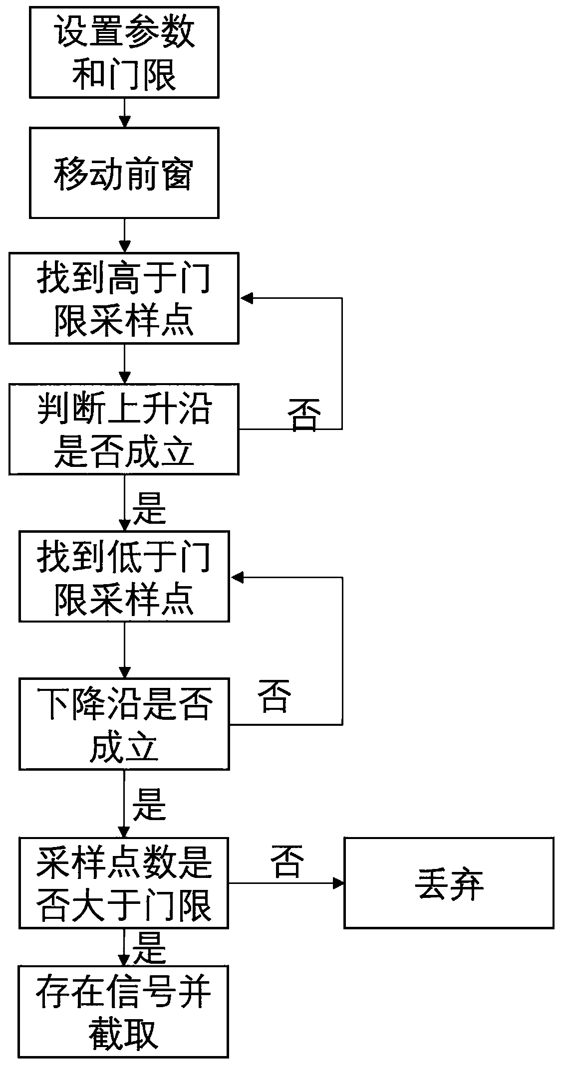
[0025] Such as figure 1 As shown, the present invention discloses a real-time detection method for radar signals, which compares the average amplitude of N sampling points before a certain moment with the amplitude of the sampling points at this moment. If the amplitude of a point is continuously higher than the average amplitude in a certain period of time before, it is considered that there is a rising edge of the signal at this moment; conversely, if the amplitude of several consecutive sampling points after a certain moment is lower than the previous average amplitude At a certain value, it is considered that there is a falling edge at this moment; when both the falling edge and the rising edge exist, the signal part existing in the data can be immediately intercepted.

[0026] The radar signal real-time detection method of the present invention is specifically as follows:

[0027] Step 1. DSP (Digital Signal Processor) starts to continuously collect the signal received in a c...


PUM


Abstract

The invention relates to a radar signal real-time detection method. The method is characterized by comparing an average amplitude of N sampling points before a certain moment with the amplitude of thesampling point at the moment, and if the amplitudes of the plurality of sampling points after starting of the certain moment are continuously a certain value higher than the average amplitude in a previous certain period of time, considering that a signal rising edge exists at the moment; otherwise, if the amplitudes of the plurality of continuous sampling points after a certain moment is startedare a certain value lower than the previous average amplitude, considering that a falling edge exists at the moment; and when both the falling edge and the rising edge exist, intercepting a signal part existing in data immediately. Whether a signal exists is detected in a mode of judging the rising edge and the falling edge in a time domain, and an effect of detecting the signal in real time under a passive condition can be achieved by setting reasonable parameters and thresholds.

Description

Technical field [0001] The invention relates to the field of radar technology, in particular to a method for real-time detection of radar signals. Background technique [0002] Traditional radar detection first needs to perform pulse compression processing on the echo signal, and convolve the echo signal with the reference signal. In actual processing, we usually perform FFT (Fast Fourier Transformation) calculation on the collected echo signal and reference signal, multiply the two frequency domain signals, and then perform IFFT (Inverse Fast Fourier Transformation) calculation to obtain the pulse pressure result. After deduction, the signal s after pulse pressure can be obtained 0 (t) is: [0003] [0004] It can be seen that the pulse pressure signal has a peak in the time domain, and the echo signal can be detected by setting the reference unit and the protection unit to detect whether the peak exists. However, this CFAR detection requires post-processing of the received sign...

Claims


Application Information

Patent Timeline
Patent Type & Authority Applications(China)
IPC IPC(8): G01S7/292G01R29/027
CPCG01R29/027G01R29/0273G01R29/0276G01S7/2927
Inventor 崔子健梅发国邓振淼
Owner XIAMEN UNIV
Why Eureka
Try Eureka