8-shaped traveling wave type linear ultrasonic motor and platform feeding device

A linear ultrasonic motor, 8-shaped technology, applied in the direction of generator/motor, piezoelectric effect/electrostrictive or magnetostrictive motor, electrical components, etc., can solve the problem of rare ultrasonic motor, low drive efficiency, and output direction Inconsistency and other problems, to achieve the effect of more synchronous output, convenient installation and fixing, and strong driving ability

Pending Publication Date: 2019-11-26
NUAA SUPER CONTROL TECHNOLOGY CO LTD
View PDF2 Cites 0 Cited by
  • Summary
  • Abstract
  • Description
  • Claims
  • Application Information

AI Technical Summary

Problems solved by technology

for image 3 In the ring beam type traveling wave linear ultrasonic motor shown, the ring beam type metal elastic body (vibrator) is an asymmetric structure, and the frequency consistency of the two vibration modes of the same order is poor, and it is impossible to couple at the same frequency. traveling waves for good driving action; and Figure 4 , Figure 5 The square circular and long annular traveling wave linear ultrasonic motors shown have a relatively more symmetrical structure, but their clamping and fixing methods are basically the same as the previous ones, directly fixing the ring beam metal elastic body (vibrator), See its utility model for details (authorized announcement numbers CN2794032Y and CN2784129Y); in fact, this ring beam metal elastic body (vibrator) has no relatively fixed nodes (nodes with approximately zero vibration), and directly clamps the ring beam metal elastic body. The elastic body (vibrator) has a great weakening effect on the amplitude of its vibration, which leads to poor driving ability and low driving efficiency
in addition Figure 4 , Figure 5 For the square-circle and long-ring traveling-wave linear ultrasonic motors shown, the directions of travelling-wave movement on the straight lines on both sides of the symmetry are opposite ( Image 6 Shown is a schematic diagram of the traveling wave motion direction of the straight line segments on both sides of the long annular stator elastic body), there is a problem of inconsistent output directions, therefore, if you want to use it to drive the platform movement, the same platform cannot be driven by traveling waves on the two straight line segments at the same time, That is, the mover can only be pressed on one of the straight line segments. At this time, the force on the stator elastic body is asymmetrical. One of the straight line segments is under preload, and the other straight line segment is suspended in the air without force; the half of the stator elastic body suspended in the air without force is in the Under the same high voltage and the same vibration frequency, piezoelectric ceramic sheets are more prone to cracking problems
Although we can reduce the probability of piezoceramic fragmentation by limiting the operating voltage (the actual operating voltage is lowered by one level) and limiting the operating frequency (making the operating frequency farther away from the resonance frequency, the actual operating frequency range becomes narrower), but because Without solving the problem from the root, this potential safety hazard still reduces the reliability of the motor to a certain extent; and this solution also brings another problem, the voltage is too low and the frequency range is too narrow, which will lead to the inability of the ultrasonic motor to fully play Its proper output performance
Therefore, the practical application of this ultrasonic motor at home and abroad is still extremely rare.

Method used


Image

  • 8-shaped traveling wave type linear ultrasonic motor and platform feeding device
  • 8-shaped traveling wave type linear ultrasonic motor and platform feeding device
  • 8-shaped traveling wave type linear ultrasonic motor and platform feeding device

Examples


Embodiment Construction

[0065] The present invention is described in further detail now in conjunction with accompanying drawing. These drawings are all simplified schematic diagrams, which only illustrate the basic structure of the present invention in a schematic manner, so they only show the configurations related to the present invention.

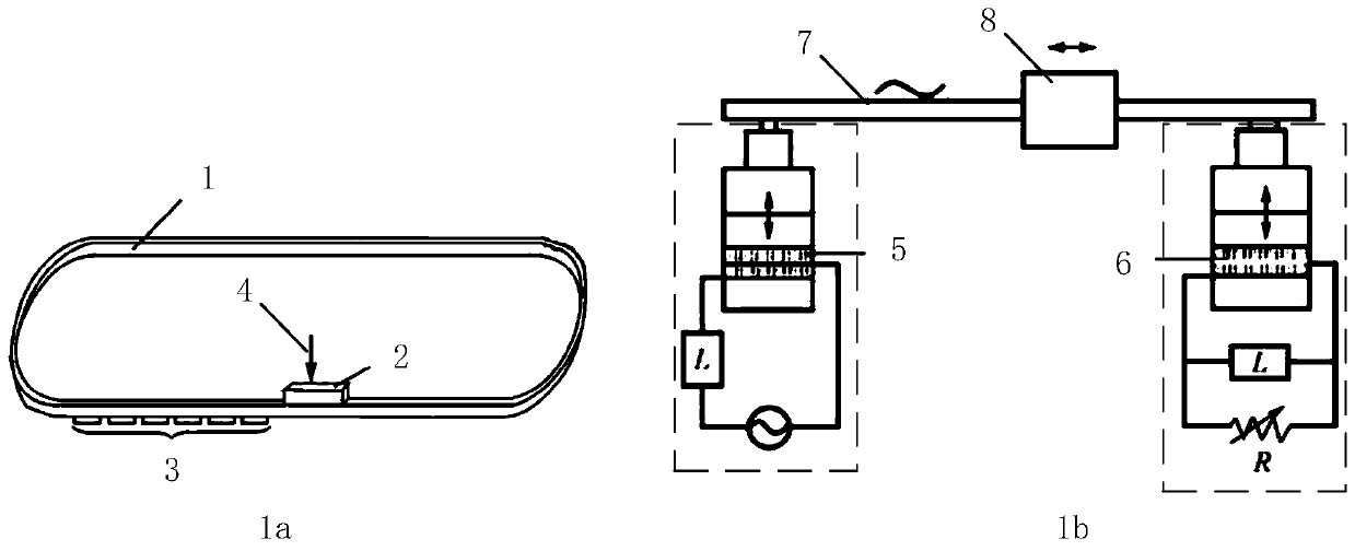
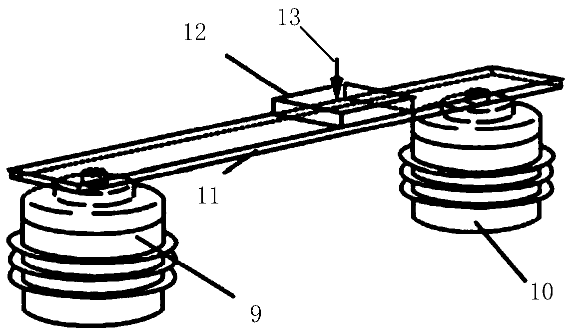
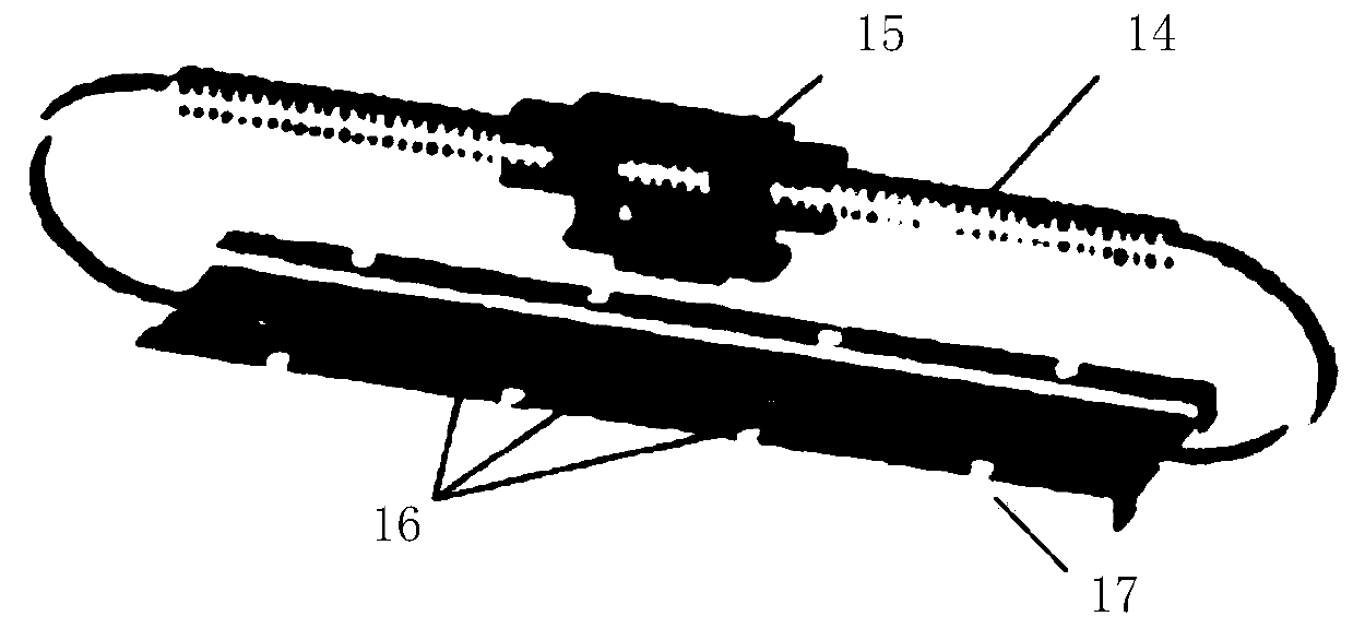
[0066] Such as Figure 7-Figure 16As shown, the characteristic components involved in the present invention include the following: 30 is the stator assembly, 301 is the stator elastic body, 302 is the 8-shaped piezoelectric ceramic sheet, 303 is the flexible printed board, 304a, 304b, 304c are friction materials, 3011 3012 is a straight line section, 3012 is a circular arc section, 3013 is a number of toothed structures on the surface of the straight line section, 3014 is a number of toothed structures on the surface of the circular arc section, 3015 is a flexible web, and 3016 is a counterweight structure (fixed installation structure) 3028a, 3028b are the u...


PUM


Abstract

The present invention relates to an 8-shaped traveling wave type linear ultrasonic motor and a platform feeding device. A stator assembly includes a friction material, a stator elastomer, a piezoelectric ceramic piece and a flexible printed circuit board; the stator elastomer includes three linear segments parallel to each other; a distance formed between two adjacent linear segments is equal, andends of two adjacent linear segments are connected smoothly via arc segments to form a sealed 8-shaped structure; with the linear segment located at a middle position as a symmetric axis, adjacent arc segments are also symmetric; a surface of each linear segment is higher than a surface of each arc segment; the piezoelectric ceramic piece is matched with the stator elastomer in shape and partitioned for polarization; movers are suspended on surfaces of the linear segments of the stator elastomer; and a contact portion of each mover with the stator elastomer is a transverse portion of an I-shaped structure. According to the 8-shaped traveling wave type linear ultrasonic motor and the platform feeding device provided by the present invention, the stator elastomer is stressed more symmetrically, the fragmentation probability of the piezoelectric ceramic piece is reduced, the output thrust force and self-locking force are larger, the output efficiency is higher, and more excellent stability and controllability are achieved.

Description

technical field [0001] The invention relates to an 8-shaped traveling wave linear ultrasonic motor and a platform feeding device, belonging to the technical field of ultrasonic motors. Background technique [0002] Ultrasonic motor is a brand-new micro-motor developed in the 1980s. Its working principle is to use the inverse piezoelectric effect of the piezoelectric ceramic sheet to excite the micro-amplitude vibration of the elastomer stator in the ultrasonic frequency domain, and through The friction between the stator (elastic body) and the mover converts the micro-vibration into the macroscopic rotational motion of the rotor, output power, and drives the load; ultrasonic motors can be divided into rotary type and linear type according to the output mode of motion, and linear ultrasonic motors According to the method of converting ultrasonic vibration into a driving force along a certain direction, it can be divided into two categories: traveling wave type and standing wa...

Claims


Application Information

Patent Timeline
Patent Type & Authority Applications(China)
IPC IPC(8): H02N2/08H02N2/04
CPCH02N2/04H02N2/08
Inventor 杨模尖杨淋赵淳生唐思宇
Owner NUAA SUPER CONTROL TECHNOLOGY CO LTD
Why Eureka
Try Eureka