
Superconducting resonating cavity and method of production thereof

A technology of superconducting radio frequency and welding parts, which is applied in laser welding equipment, resonators, welding equipment, etc., and can solve problems such as inconsistent results

Pending Publication Date: 2019-11-26
II VI特拉华公司
View PDF9 Cites 0 Cited by
  • Summary
  • Abstract
  • Description
  • Claims
  • Application Information

AI Technical Summary

Problems solved by technology

Although this process is well studied and controlled, it can still produce inconsistent results

Method used


Image

  • Superconducting resonating cavity and method of production thereof
  • Superconducting resonating cavity and method of production thereof
  • Superconducting resonating cavity and method of production thereof

Examples


Embodiment Construction

[0033] Various non-limiting examples will now be described with reference to the drawings, wherein like reference numerals correspond to identical or functionally equivalent elements.

[0034] In the following text, for the convenience of description, the terms "end", "upper", "lower", "right", "left", "vertical", "horizontal", "top", "bottom", "transverse", "longitudinal" and its derivatives shall denote each instance as oriented in the drawings. However, it should be understood that the examples may employ various alternative modifications and step sequences unless expressly indicated to the contrary. It is also to be understood that the specific examples shown in the drawings and described in the following specification are merely illustrative examples or aspects of the invention. Therefore, specific examples or aspects disclosed herein are not to be construed as limiting.

[0035] Having described prior art cells 4 and SRF chambers 2 using one or more of said cells 4, th...


PUM


Abstract

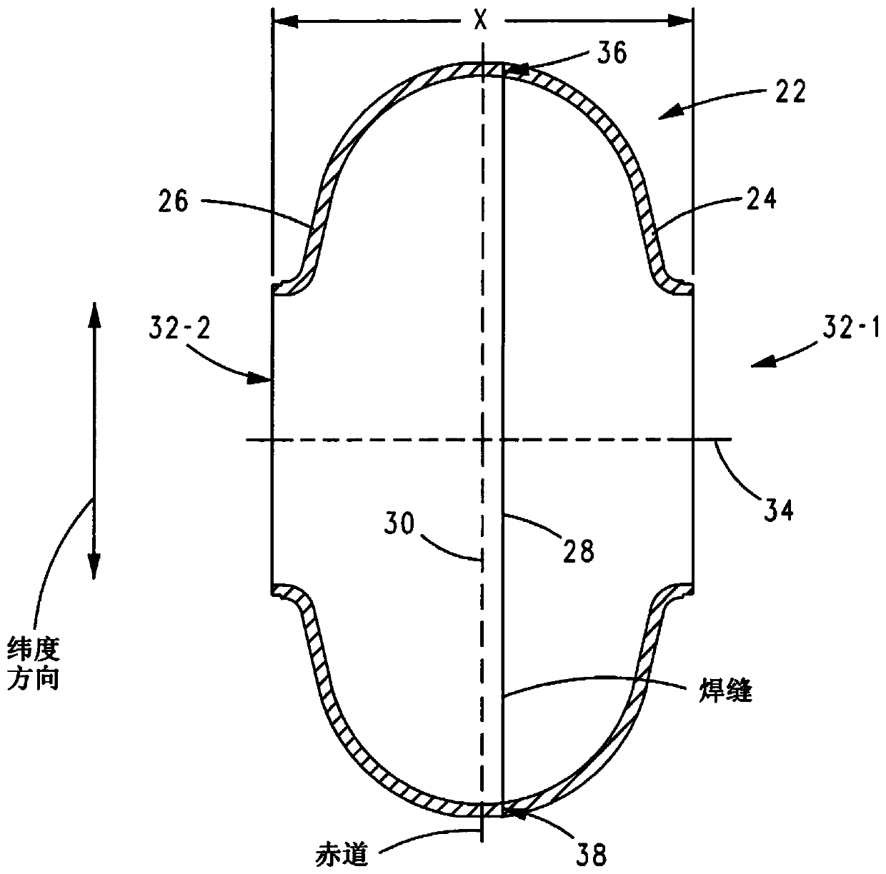
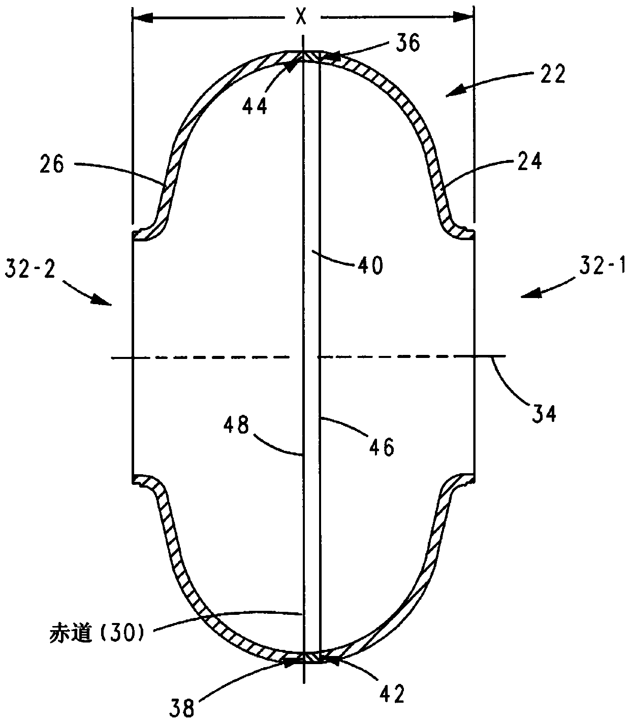
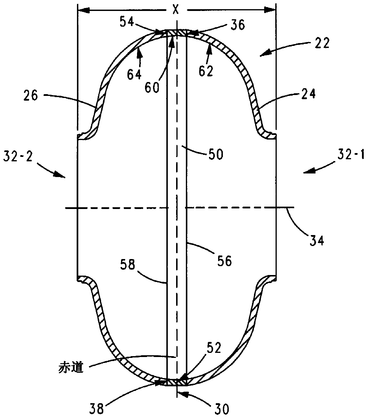
The invention reveals a superconducting radio frequency unit. The superconducting radio frequency unit includes a body defining a hollow cavity, the body having first and second apertures, an axis atopposite ends of the body, and an equator extending between the first and second apertures, and surrounding the axis between the first and second apertures. The body includes at least a first weld that surrounds the axis at a location on the body spaced apart from the equator. Each of the weld seams extends through the body and has opposite sides terminating near the inside and outside of the body, and each of the weld seams includes a first conductive weld portion formed on one side of the weld seam and a second weld portion formed on the opposite side of the weld seam. The second weld may bea conductive weld, a piercing weld, or a transition weld.

Description

technical field [0001] The present invention relates to superconducting radio frequency (SRF) cells, methods of making SRF cells, welds that may be used with SRF cells or other objects, and methods of forming welds. Background technique [0002] An RF cavity is used to accelerate a population of charged particles towards a target. For many applications, the benefits of using a cavity with superconducting inner surfaces far outweigh the added cost of cooling the cavity to cryogenic temperatures. Cavities are evaluated by quality factor and acceleration gradient. Quality factor (Q 0 ) gives the inverse of the amount of energy lost in each cycle of the system. A high figure of merit reduces operating costs by requiring less cryogenic cooling. The acceleration gradient of a cavity describes its ability to accelerate particles. The acceleration gradient of a superconducting RF (SRF) cavity is usually given in megavolts / meter. Higher gradients require fewer chambers to opera...

Claims


Application Information

Patent Timeline
Patent Type & Authority Applications(China)
IPC IPC(8): H05H7/20
CPCH05H7/20H01P7/06H01P11/008B23K26/28B23K2103/50B23K26/282B23K2101/36
Inventor 艾伦·郝杰士凯尔·布兰尼根
Owner II VI特拉华公司
Learn More