Cryoablation needle with adjustable target area

An ablation needle and targeting technology, which is applied in the field of cryoablation needles, can solve the problems of complicated treatment operations, easy injury and surrounding healthy tissues, and achieve the effects of smooth air return, avoiding cold loss, and preventing frostbite

Pending Publication Date: 2019-11-29
ACCUTARGET MEDIPHARMA (SHANGHAI) CO LTD
View PDF0 Cites 4 Cited by
  • Summary
  • Abstract
  • Description
  • Claims
  • Application Information

AI Technical Summary

Problems solved by technology

[0004] The purpose of the present invention is to provide a cryoablation needle with an adjustable target area, so as to solve the technical problems of the

Method used


Image

  • Cryoablation needle with adjustable target area
  • Cryoablation needle with adjustable target area
  • Cryoablation needle with adjustable target area

Examples


Example Embodiment

[0073] Example 1

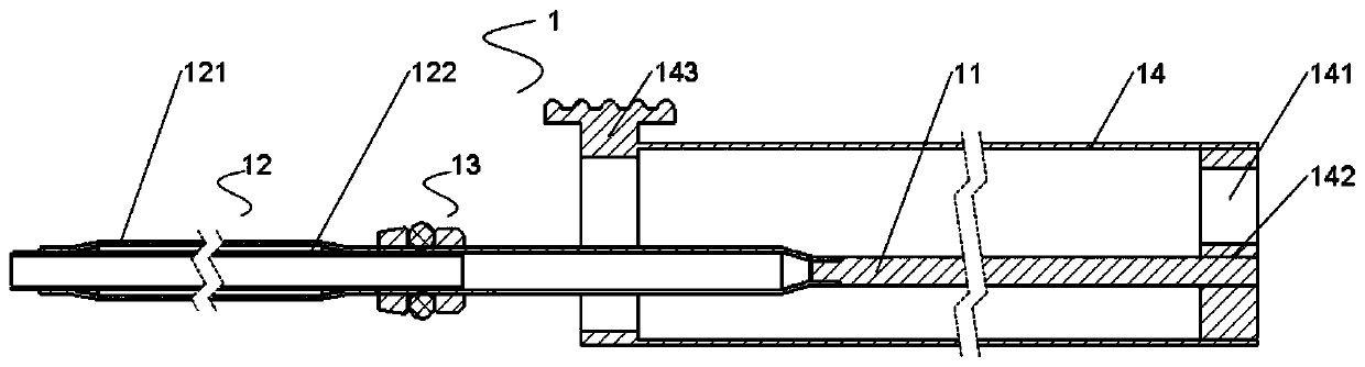
[0074] Please refer to image 3 , the tube wall of the front section heat insulation pipe 12 can be made of heat insulating material, also can adopt double-layer vacuum wall, the present invention does not make specific limitation, present embodiment preferably double-layer vacuum wall, namely described front section heat insulation pipe 12 comprises The front-section inner tube 122 and the front-section outer tube 121 form a vacuum interlayer between the front-section inner tube 122 and the front-section outer tube 121 .

[0075] As an embodiment, both ends of the front-section outer tube 121 are shrinked and vacuum-welded with the front-section inner tube 122 to form a permanent vacuum interlayer;

[0076] As another embodiment, both ends of the front-section inner tube 122 are flared and vacuum-welded with the front-section outer tube 121 to form a permanent vacuum interlayer;

[0077] As a third embodiment, the two ports of the front-section inner tube...

Example Embodiment

[0100] Example 2

[0101] Please refer to Figure 15 and Figure 16 , when the return air temperature of the cryoablation needle is not too low, the air return pipe 25 can be overlaid on the air intake pipe 243, Figure 11 It is the rear structure of the adjustable targeting area 3 of this type of cryoablation needle, and the structure not shown in the figure is the same as Figure 9 , Figure 10 unanimous. The rear end of the rear section inner pipe 222 of this structure is in an open state, only the air intake pipe 243 is fixedly connected to the rear section inner pipe 222 and gets final product, the return air pipe 25 is enclosed within the rear portion of the handle 26, and the air intake pipe 243 is located at the return air pipe 25 internal. The rear end sealing assembly 23 of this structure is a rear end sealing ring assembly, and the rear end sealing ring assembly is fixed on the outside of the rear end of the rear heat insulation pipe 22, between the rear heat i...

Example Embodiment

[0103] Example 3

[0104] In order to monitor the working status of the cryoablation needle and the central temperature of the frozen area in real time, the cryoablation needle needs to have a real-time temperature measurement function inside the target area. like Figure 17 As shown, the temperature measuring wire 271 can be led out through the gap of the fin tube 242. The fixed part 22 of this solution also includes a wire assembly 27, and the wire assembly 27 includes a temperature measuring wire 271 and a wire lead-out tube 272. The temperature measuring wire 271 The temperature measuring point 2711 is placed at the front end of the J-T groove 241, and the temperature measuring line 271 passes through the inner tube 122 of the front section, the return air groove 1331, and the gap between the finned tube 242 (the finned tube 242 is wound on the core with a certain pitch. On the shaft 11, the temperature measuring line 271 does not penetrate into the tube of the finned tub...


PUM


Abstract

The invention relates to a cryoablation needle with an adjustable targeting area. The cryoablation needle comprises an adjusting part and a fixing part, the adjusting part can axially move relative tothe fixing part to adjust a length of a target area, the fixing part comprises a needle rod, a rear-section heat insulation pipe, an air inlet pipe fitting and an air return pipe, the rear end of theneedle rod is fixedly connected with the front end of the rear-section heat insulation pipe, and the needle rod and the rear-section heat insulation pipe are communicated to form an accommodating cavity; the air inlet pipe fitting and the air return pipe are inserted into the accommodating cavity from the rear end of the rear-section heat insulation pipe; the adjusting part comprises a front-section heat insulation pipe and a core shaft, and the front-section heat insulation pipe is axially arranged in the accommodating cavity in a sliding mode so as to adjust the length of the target area; the air inlet pipe fitting penetrates through the front-section heat insulation pipe and extends into the needle rod; the core shaft is inserted from the rear end of the rear-section heat insulation pipe and is linked with the front-section heat insulation pipe. By means of the cryoablation needle, the technical problems that due to the fact that the target area of the existing cryoablation needleis fixed, treatment operation is complex, and surrounding healthy tissue is prone to being injured are solved.

Description

technical field [0001] The invention relates to a cryoablation needle, in particular to a cryoablation needle with an adjustable target area. Background technique [0002] Cryoablation, a treatment modality that uses low temperatures to destroy diseased tissue, is considered an efficient and minimally invasive method for treating malignant tumors. The cryoablation technique is easy to operate, has few complications, and is effective in analgesia. Moreover, the boundary of the ice ball formed by ablation is clear and easy to observe, and it can safely ablate lesions near large blood vessels or important organs. Cryoablation can also adopt the method of multi-needle freezing, so that the ablation range is wider, and it is suitable for large lesions and lesions with irregular shapes. [0003] The target area (that is, the effective freezing area) is located at the front of the cryoablation needle, and its length determines the size of the freezing range. The longer the target ...

Claims


Application Information

Patent Timeline
IPC IPC(8): A61B18/02
CPCA61B18/02A61B2018/00577A61B2018/00791A61B2018/0231A61B2018/0293
Inventor 杨迟徐彬凯吴银龙常兆华
Owner ACCUTARGET MEDIPHARMA (SHANGHAI) CO LTD
Why Eureka
Try Eureka