Dust removing device for optical fiber diameter measuring instrument

A technology of dust removal device and caliper, which is applied in the field of optical fiber and core rod manufacturing, and can solve problems such as cost loss, miscutting of optical fiber, waste, etc.

Pending Publication Date: 2019-11-29
JIANGSU HENGTONG OPTICAL FIBER TECH +1
View PDF0 Cites 0 Cited by
  • Summary
  • Abstract
  • Description
  • Claims
  • Application Information

AI Technical Summary

Problems solved by technology

For example, during the drawing process, the optical fiber is controlled by a fiber optic caliper. The dust and impurities on the surface of the fiber optic caliper will easily cause false alarms of the coating diameter after the fiber is drawn, resulting in an emergency stop of the process. Prolonged alarming will lead to Qualified products are misjudged as defective products, resulting in the miscutting of normal optical fibers, resulting in a large amount of waste, and the problem of false alarms caused by the diameter measuring instrument if the dust is not dealt with in time during the core rod extension process
Based on this, if the dust and impurities on the surface of the optical fiber caliper are not treated in time, it will not only affect the production efficiency of the optical fiber, but also cause irreversible cost losses.

Method used


Image

  • Dust removing device for optical fiber diameter measuring instrument
  • Dust removing device for optical fiber diameter measuring instrument
  • Dust removing device for optical fiber diameter measuring instrument

Examples


Embodiment

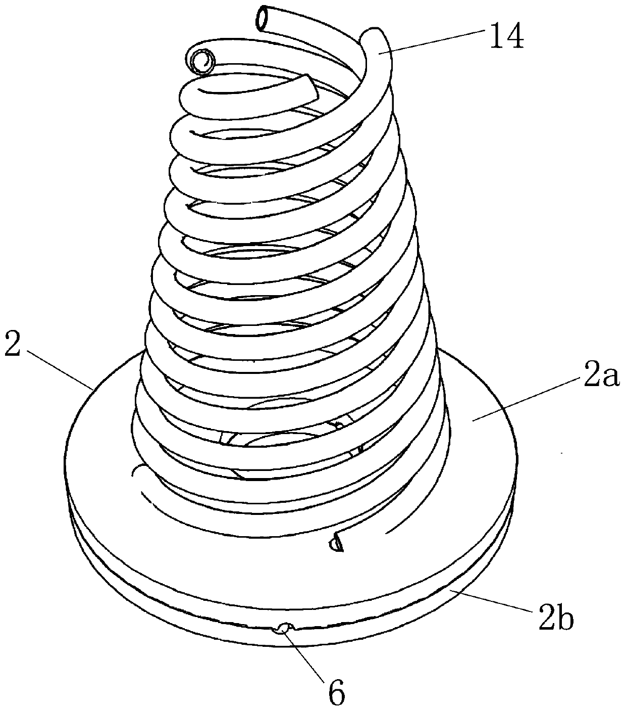
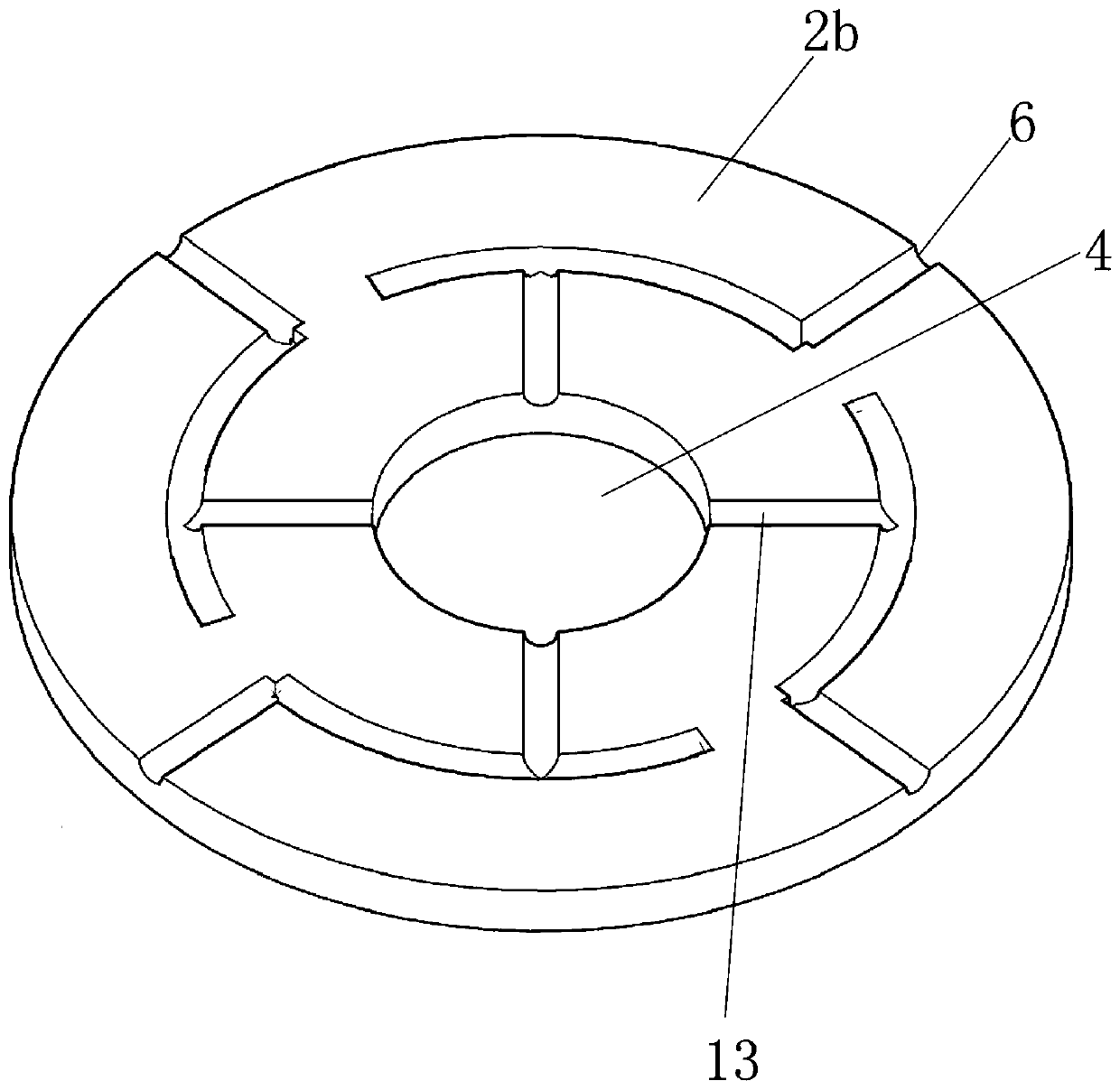
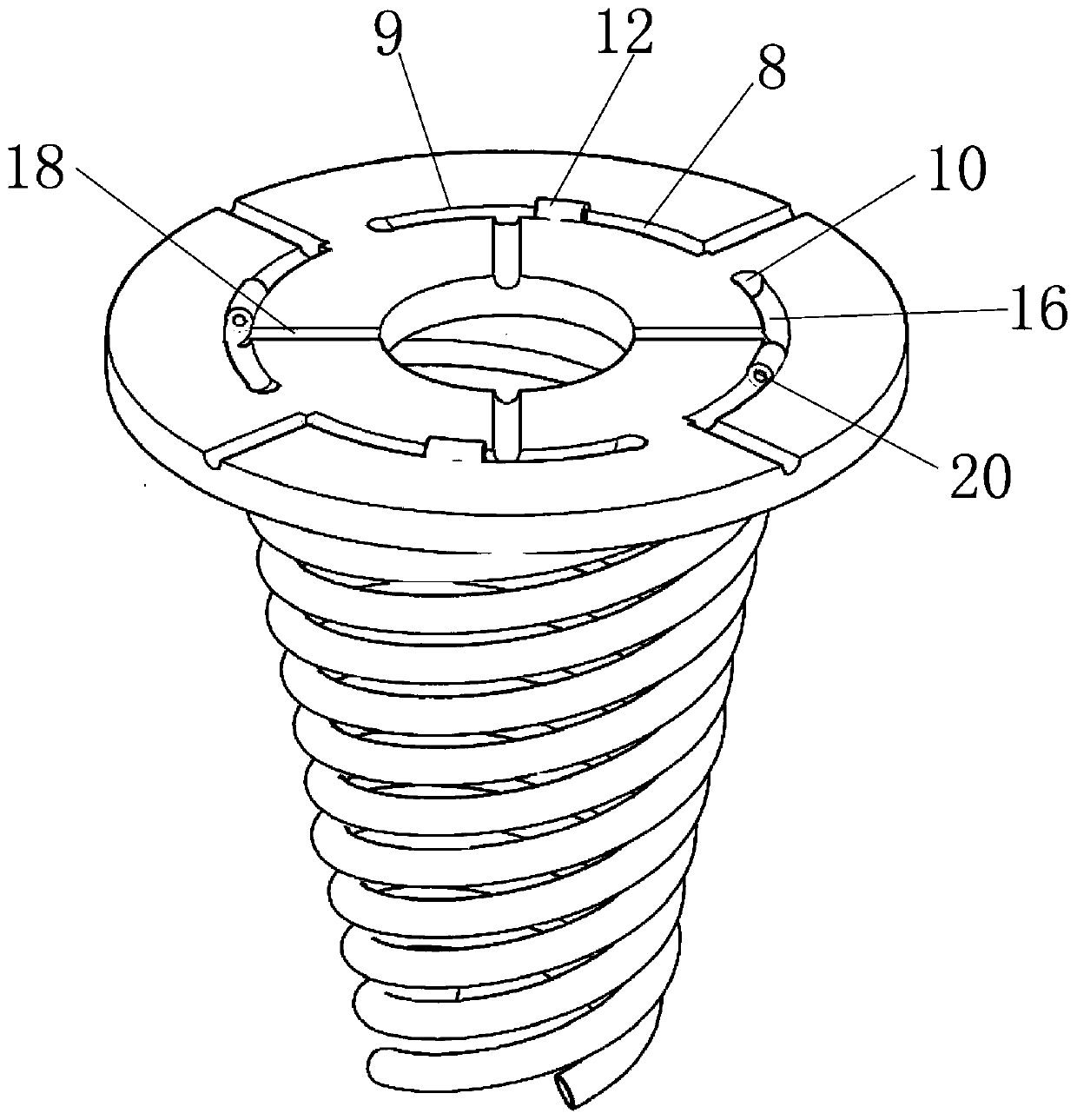
[0023] This embodiment discloses a dust removal device for an optical fiber caliper. The dust removal device includes an end cover 2, which is assembled with the optical fiber caliper through the bottom surface of the end cover 2; refer to Figure 1~3 As shown, the center of the above-mentioned end cap 2 is provided with a fiber hole 4; the flat bottom surface of the above-mentioned end cap 2 is assembled on the optical fiber caliper, and the bare fiber after fiber drawing passes through the fiber hole 4 and enters the fiber caliper .

[0024] The outer wall of the above-mentioned end cover 2 is provided with at least two groups of air inlets 6, and the above-mentioned air inlets 6 communicate with the air flow channel inside the end cover 2, and the end of the above-mentioned air flow channel communicates with the air outlet 10; The air port 6 is independently configured with an air flow channel, and a group of air outlets 10 is independently configured on the above-mentioned...


PUM


Abstract

The invention discloses a dust removing device for an optical fiber diameter measuring instrument. The dust removing device comprises an end cover, wherein a fiber through hole is formed in the centerof the end cover. At least two air inlets are formed in the outer wall of the end cover, the air inlets communicate with air flow channels in the end cover, and the air flow channels communicate withair outlets. The end cover is internally provided with the air flow channels corresponding to the air inlets respectively and provided with the air outlets corresponding to the air flow channels respectively. Each air flow channel is internally provided with an air flow conversion component, and the air flow conversion components divide the airflow channels into first air flow channel bodies andsecond air flow channel bodies. The first air flow channel bodies and the second air flow channel bodies communicate with the air inlets and the air outlets respectively. The end cover is internally provided with adsorption channels communicating with the second air flow channel bodies and communicating with the fiber through hole. The ventilation aperture of the air flow conversion components issmaller than that of the first air flow channel bodies. The dust removing device for the optical fiber diameter measuring instrument is used for removing dust and impurities on the surface of the optical fiber diameter measuring instrument online, performs two-step cleaning on online drawn optical fibers and core rods in the extending process, and reduces the influence of the dust and the impurities on the production efficiency and quality of the optical fibers.

Description

technical field [0001] The invention relates to the field of optical fiber and core rod manufacturing, in particular to a dust removal device for an optical fiber caliper. Background technique [0002] The arrival of the 5G era shows that the optical communication industry is constantly developing leanly in line with people's growing needs. The optical fiber industry accepts the opportunities and challenges brought by the development of science and technology, and gradually promotes high-efficiency and low-loss manufacturing methods to meet the harsh market environment. Dust particles and exhaust emissions have always been important factors affecting the efficiency, quality and cost of fiber optic production. For example, during the drawing process, the optical fiber is controlled by a fiber optic caliper. The dust and impurities on the surface of the fiber optic caliper will easily cause a false alarm of the coating diameter after the fiber is drawn, resulting in an emerge...

Claims


Application Information

Patent Timeline
Patent Type & Authority Applications(China)
IPC IPC(8): B08B5/04
CPCB08B5/04
Inventor 郭健张琬祺王林李永通卢萍王明轩王亚玲崔晓冬姚之圃汪修权贲庆超李辉袁建超雷鸣
Owner JIANGSU HENGTONG OPTICAL FIBER TECH
Why Eureka
Try Eureka