Durable hydraulic cylinder
A hydraulic cylinder and durable technology, applied in the field of hydraulic cylinders, can solve the problems of broken connection between the cylinder head and the front rod, low thread connection strength, etc., and achieve the effects of long service life, not easy to break, and high structural strength
- Summary
- Abstract
- Description
- Claims
- Application Information
AI Technical Summary
Problems solved by technology
Method used
Image

Examples
Embodiment 1
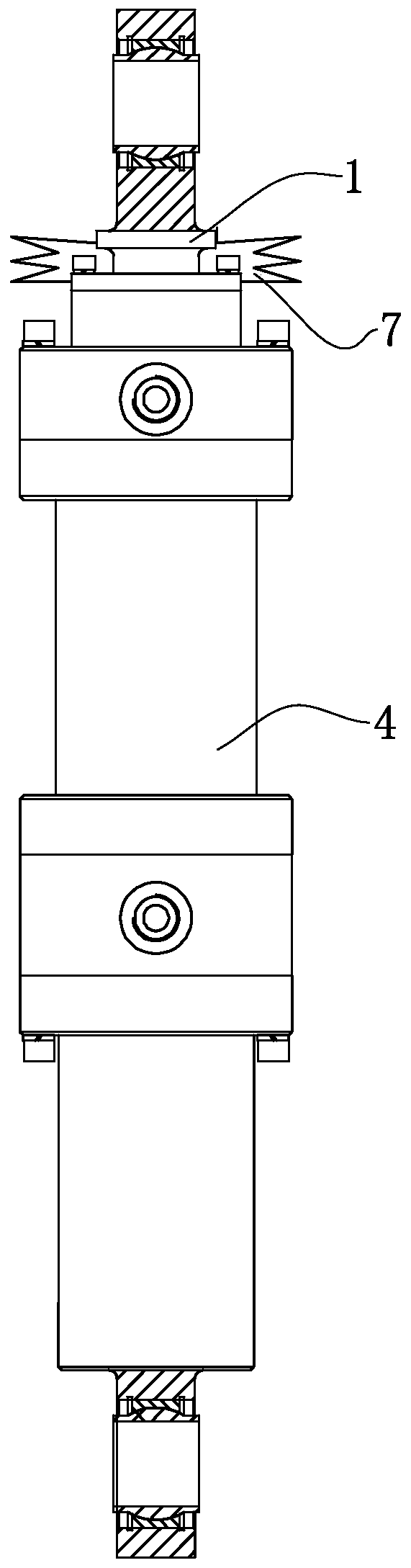
[0042] refer to figure 1 , discloses a durable hydraulic cylinder for the present invention, comprising a casing 4, one end of the casing 4 is slidably connected with a piston rod 1 moving along its axial direction, and the end of the casing 4 facing away from the piston rod 1 is welded with a cylinder tail earring 5.
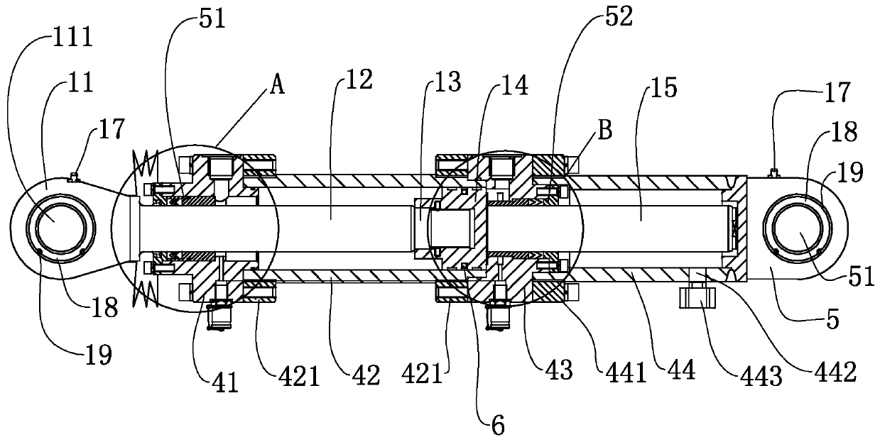
[0043] refer to figure 2 and image 3 , the shell 4 includes a cylinder head 41, the cylinder head 41 is detachably connected with a cylinder barrel 42, the cylinder barrel 42 is detachably connected with a cylinder tail 43, and the cylinder tail 43 is detachably connected with a cylinder body 44; the cylinder head 41, the cylinder barrel 42. Cylinder tail 43 and cylinder body 44 are circular tubes with overlapping centerlines. Cylinder head 41, cylinder barrel 42, cylinder tail 43 and cylinder body 44 are detachably connected in turn.
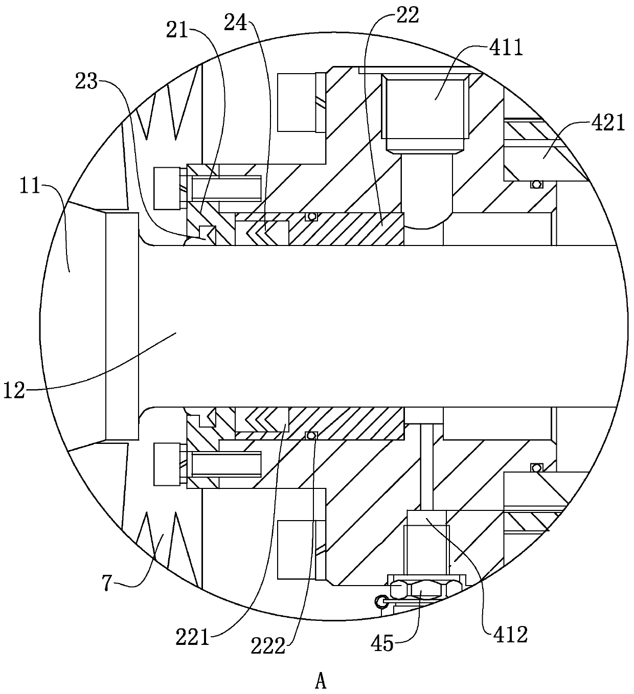
[0044] refer to figure 2 , image 3 and Figure 6 , the structure of the cylinder head 41 is a circular tube, and the ...
PUM
 Abstract
Description
Claims
Application Information
PatSnap Eureka turns technology decisions into work you can execute. Powered by our Innovation Knowledge Graph, it runs expert workflows across engineering, life sciences, materials and intellectual property. Get your review-ready output in minutes.


