
Speed reducer for eccentric driving and double-stage planar oscillating tooth gear

A movable tooth reducer and eccentric drive technology, which is applied in transmission devices, transmission device parts, gear transmission devices, etc., can solve problems such as inability to guarantee high efficiency, achieve elimination of backlash of meshing pairs, high transmission efficiency, and wide application range Effect

Active Publication Date: 2019-11-29
YANSHAN UNIV
View PDF4 Cites 7 Cited by
  • Summary
  • Abstract
  • Description
  • Claims
  • Application Information

AI Technical Summary

Problems solved by technology

Although the current planar movable tooth transmission can achieve small size and large transmission ratio, it cannot guarantee high efficiency. Therefore, it is necessary to design a reducer with both large transmission ratio and high efficiency to be suitable for more new technologies and new equipment. development needs

Method used


Image

  • Speed reducer for eccentric driving and double-stage planar oscillating tooth gear
  • Speed reducer for eccentric driving and double-stage planar oscillating tooth gear
  • Speed reducer for eccentric driving and double-stage planar oscillating tooth gear

Examples


Embodiment Construction

[0024] The following will clearly and completely describe the technical solutions in the embodiments of the present invention with reference to the drawings in the embodiments of the present invention. Based on the embodiments of the present invention, all other embodiments obtained by persons of ordinary skill in the art without making creative efforts belong to the protection scope of the present invention.

[0025] It should be noted that, unless otherwise specified, the technical terms or scientific terms used in this application shall have the usual meanings understood by those skilled in the art to which the present invention belongs. For the convenience of readers, the figure 1 The orientation in , describes the device.

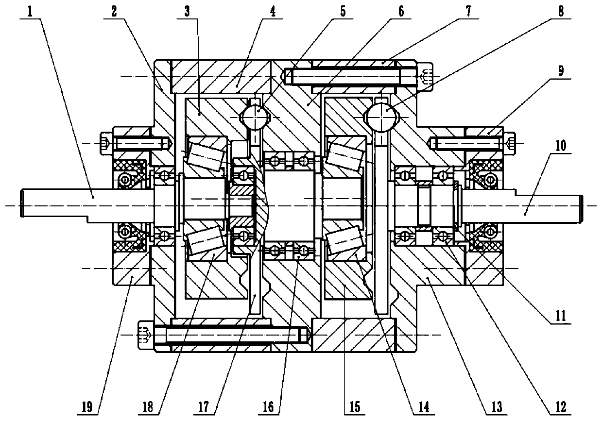
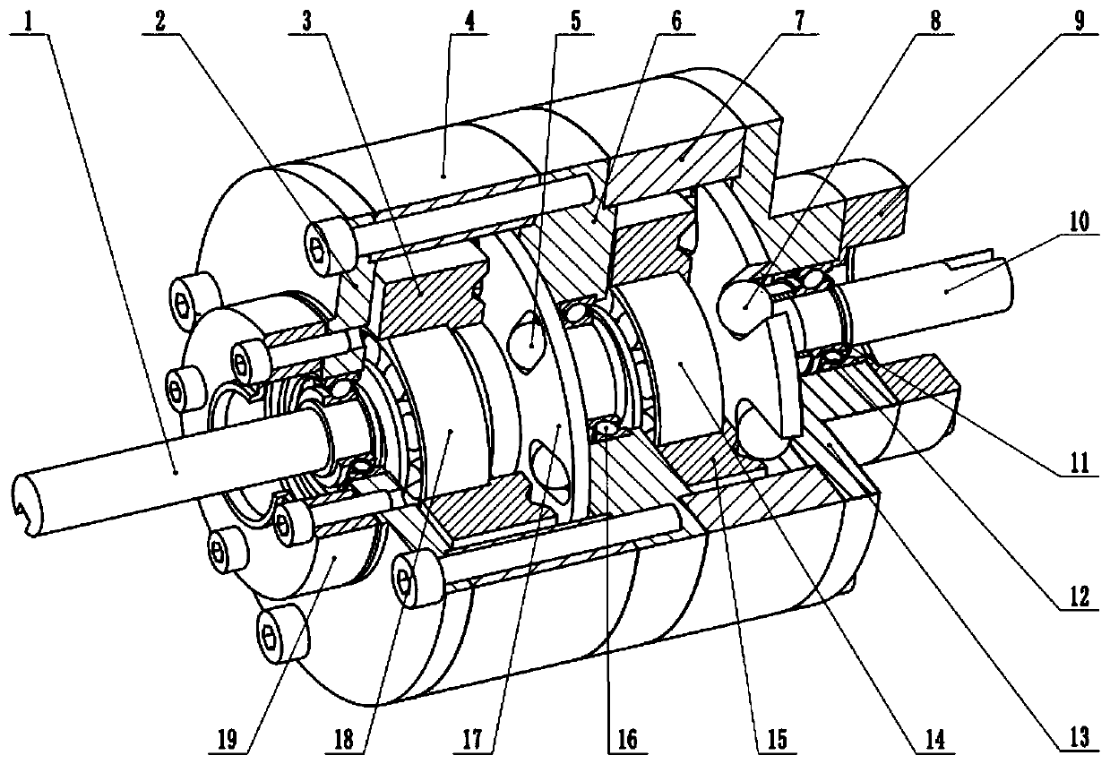
[0026] exist figure 1 , figure 2 In the schematic diagram of the eccentric drive two-stage planar movable gear reducer shown, it includes the drive shaft 1, the first housing 2, the first-stage shock wave device 3, the middle housing 4, the first-s...


PUM


Abstract

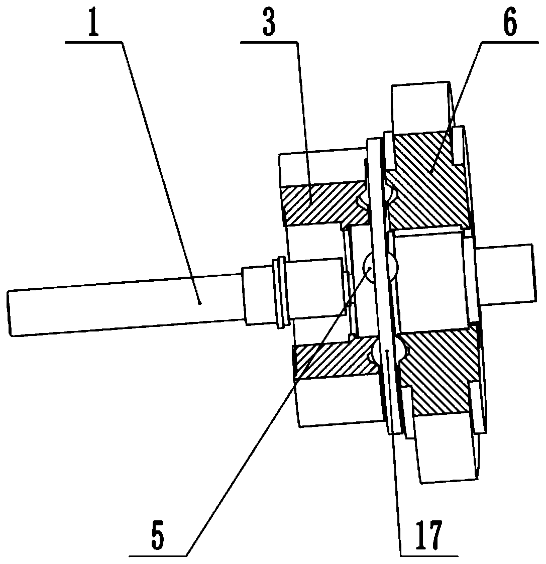
The invention relates to a speed reducer for an eccentric driving and double-stage planar oscillating tooth gear. The speed reducer comprises a driving shaft, shock wave devices, oscillating tooth gear frames, central wheels and an output shaft. In a first-stage transmission system, a first-stage central wheel is fixed, the first-stage central wheel and a first-stage shock wave device are connected to the eccentric section of the driving shaft through a first-stage tapered roller bearing, a first-stage steel ball moves in guide grooves of a first-stage oscillating tooth gear frame through thecommon constraint of a rolling path of the first-stage shock wave device and a rolling path of the first-stage central wheel, and power is output by the first-stage oscillating tooth gear frame; and in a second-stage transmission system, a second-stage central wheel is fixed, the output of the first-stage oscillating tooth gear frame is used as the input of the second-stage transmission system, asecond-stage shock wave device is connected to the eccentric section of the first-stage oscillating tooth gear frame through a second-stage tapered roller bearing, a second-stage steel ball moves in atooth gear groove of the output shaft through the common constraint of a rolling path of the second-stage shock wave device and the a rolling path of the second-stage central wheel, and power is output by the output shaft. According to the speed reducer for the eccentric driving and double-stage planar oscillating tooth gear, the first-stage oscillating tooth gear frame adopts an integrated structure, the structure is simple and compact, a transmission ratio range of the speed reducer is wide, the application range is wide, and the transmission efficiency is high.

Description

technical field [0001] The invention relates to a movable tooth transmission device, in particular to the design and research of realizing the eccentric drive of a planar movable tooth reducer. Background technique [0002] Movable tooth transmission is a new type of transmission mechanism that is different from traditional gear transmission. With the continuous development of movable tooth transmission, many new types of movable tooth reducers have come out one after another. Planar movable tooth transmission is a very representative type of movable tooth transmission. It is widely used in aerospace, new energy, precision instruments and other fields due to its advantages of compact structure, good balance conditions and wide transmission ratio range. The new eccentric drive two-stage planar movable tooth transmission system combines the two-stage planar movable tooth transmission system. Compared with the single-stage movable tooth transmission, the transmission ratio rang...

Claims


Application Information

Patent Timeline
IPC IPC(8): F16H1/32F16H1/34F16H57/023F16H57/08F16H57/12
CPCF16H1/32F16H1/34F16H57/023F16H57/08F16H57/12F16H2001/323F16H2057/02086
Inventor 许立忠杨鲜苗叶胜康
Owner YANSHAN UNIV
Learn More