Temperature control device, method and system

A temperature control device, a technology of preset temperature, applied in thermal storage heaters, fluid heaters, lighting and heating equipment, etc., can solve problems such as exceeding the set temperature

Pending Publication Date: 2019-11-29
NANJING FORESTRY UNIV
View PDF6 Cites 3 Cited by
  • Summary
  • Abstract
  • Description
  • Claims
  • Application Information

AI Technical Summary

Problems solved by technology

[0005] The purpose of this application is to provide a temperature control device, method and system to solve the ...

Method used


Image

  • Temperature control device, method and system
  • Temperature control device, method and system

Examples


example 1

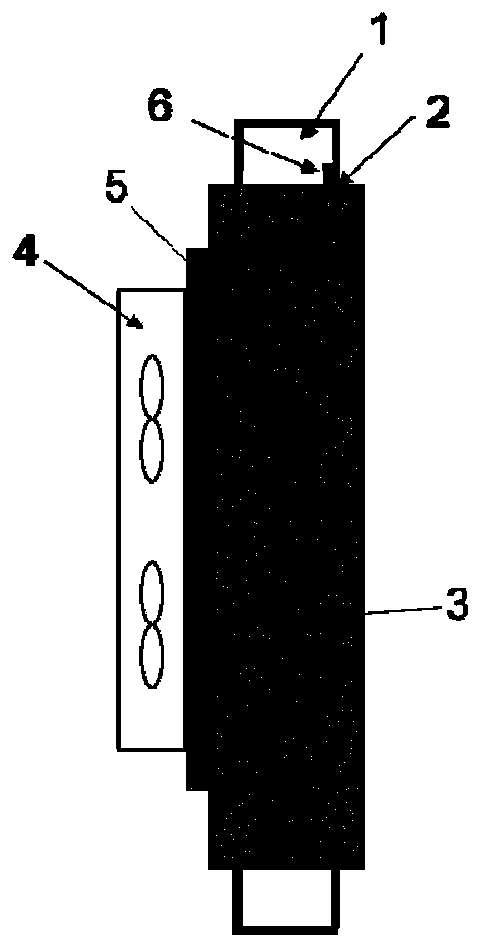
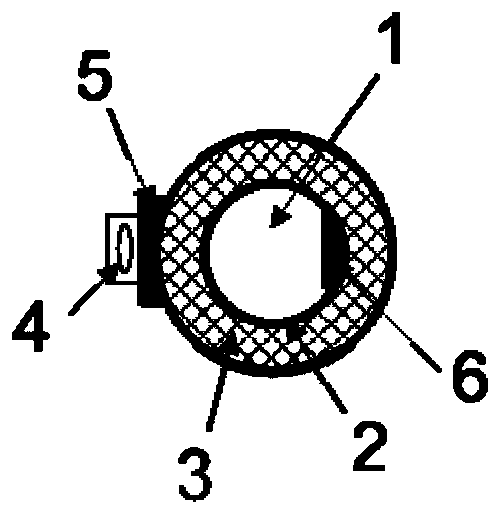
[0063] Example 1, the diameter of the pipe cavity is 6mm, the total length is 2.5m, the fluid is water, and the temperature of the fluid measured by the first sensor is 40°C. Optionally, in the phase change heat storage material filling layer, the main component of paraffin is The molecular formula is C28H58, the mass fraction is 71.5%, the mass fraction of metallic copper is 8.5%, and the mass fraction of graphite is 20%.

[0064] Take the precise temperature rise mode when the set temperature is 60°C as an example. Correspondingly, the control circuit drives the heating component to raise the temperature of the fluid in the pipeline. When the first temperature sensor detects that the temperature of the fluid in the pipeline reaches the phase change of the heat storage material point (60°C), the phase change heat storage material begins to absorb the heat emitted by the heating component, so that the heat received by the fluid is greatly reduced; according to the temperature c...

example 2

[0066] Example 2, the diameter of the pipeline cavity is 6 mm, the total length is 2.5 m, the fluid is non-methane total hydrocarbon (NMHC), and the temperature of the fluid measured by the first sensor is 100 ° C. Optionally, the phase change heat storage material 2 In the filling layer, the molecular formula of the main component of paraffin is C 30 h 62 , the mass fraction is 23.7%, the metal alloy adopts Bi(56%)-Sn(40%)-Zn(4%) composite, accounting for 68.3%, and the graphite addition accounts for 8%.

[0067] Take the rapid temperature rise mode when the set temperature is 130°C as an example. First, the control circuit drives the heating component to heat. The variable heat storage material begins to absorb the heat emitted by the heating component, so that the heat received by the fluid is greatly reduced; according to the temperature collected by the second temperature sensor and the temperature collected by the first temperature sensor, the fuzzy control algorithm is...


PUM

PropertyMeasurementUnit
Diameteraaaaaaaaaa
Total lengthaaaaaaaaaa

Abstract

The invention provides a temperature control device, method and system and relates to the technical field of temperature control. The device is arranged on the outer side of a pipeline in a winding manner through a heating assembly. The portion between the heating assembly and the pipeline is filled with a phase change heat storage material. A first temperature sensor is arranged on the inner wallof the pipeline and used for measuring the temperature of fluid in the pipeline. A second temperature sensor is arranged on the outer wall of the heating assembly and used for measuring the outside environment temperature of fluid outside the pipeline. A control circuit is electrically connected with the heating assembly, a heat dissipating assembly, the first temperature sensor and the second temperature sensor. After the fluid needing temperature control enters the pipeline, when temperature rising or temperature lowering is needed, according to the set temperature and the fluid temperaturemeasured by the first temperature sensor, the control circuit can drive the heating assembly or the heat dissipating assembly to work, and by means of the assisting function of the second temperaturesensor and the phase change heat storage material, in the fluid temperature control process, the phenomenon that the actual temperature surpasses the set temperature can be avoided.

Description

technical field [0001] The present application relates to the technical field of temperature control, in particular to a temperature control device, method and system. Background technique [0002] Temperature represents the degree of hot or cold of an object, and its definition is given by thermodynamics. It is closely related to human life, industrial and agricultural production, and scientific research. There are almost no production processes and scientific research that do not require temperature control. Therefore, temperature control devices are widely used. It is used in many fields such as metallurgical industry, chemical production, electric power engineering, paper industry, machinery manufacturing and food processing. [0003] Existing temperature control devices are mainly based on a proportional-integral-derivative (Proportion Integral Differential, PID) circuit, and the temperature control device is controlled by the PID circuit to reach a preset temperature v...

Claims


Application Information

Patent Timeline
IPC IPC(8): F24H7/02F24H9/18F24H9/20
CPCF24H7/0233F24H9/1818F24H9/2028F24H2250/02
Inventor 郑晓丹邓翔
Owner NANJING FORESTRY UNIV
Why Eureka
Try Eureka