
Airborne camera low-temperature heating system and heating method thereof

A heating system and camera technology, applied in the direction of transparent/reflective heating devices, cameras, electric heating devices, etc., can solve problems such as low work efficiency, poor environmental adaptability, complex heating circuits, etc., and achieve low maintenance and repair costs and environmental protection The effect of strong adaptability and high safety factor

Pending Publication Date: 2021-09-24
NO 55 INST CHINA ELECTRONIC SCI & TECHNOLOGYGROUP CO LTD
View PDF0 Cites 0 Cited by
  • Summary
  • Abstract
  • Description
  • Claims
  • Application Information

AI Technical Summary

Problems solved by technology

[0004] 1. The heating circuit is relatively complicated, and the probability of failure is relatively high;
[0005] 2. The heating method adopts the method of bonding the lens glass with the heating film, which affects the transmittance of the lens;
[0006] 3. The heating power cannot be adjusted in real time and dynamically according to the change of the external temperature, the heating power consumption is large, and the work efficiency is low;
[0007] 4. There is no manual heating mode, the flexibility is not high, and the environmental adaptability is poor;
[0008] 5. There is no detection circuit for the working state of the heating circuit. Once the heating fails, it cannot be fed back to the user in time, which increases the safety hazard and increases the cost of maintenance and repair in the later period.

Method used


Image

  • Airborne camera low-temperature heating system and heating method thereof
  • Airborne camera low-temperature heating system and heating method thereof
  • Airborne camera low-temperature heating system and heating method thereof

Examples


Embodiment Construction

[0036] The drawings constituting a part of the present invention are used to provide a further understanding of the present invention, and the schematic embodiments and descriptions of the present invention are used to explain the present invention, and do not constitute an improper limitation of the present invention.

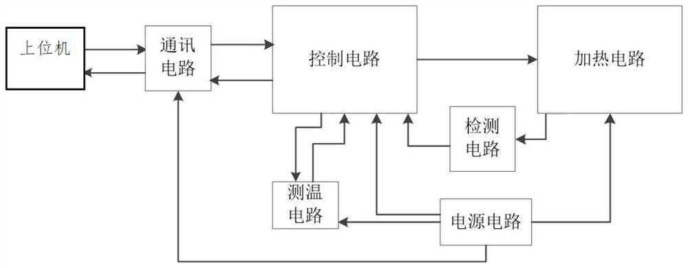
[0037] Such as figure 1 As shown, the present invention provides a low-temperature heating system for an airborne camera lens, including a control circuit, a temperature measurement circuit, a heating circuit and a power supply circuit.

[0038] The control circuit is used to receive the data information fed back by the temperature measurement circuit, and control the heating circuit to complete the heating work;

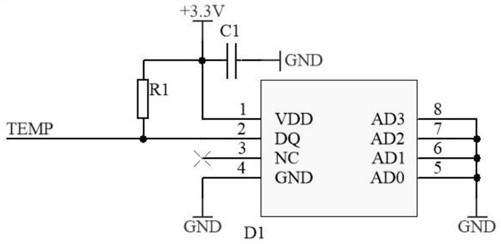
[0039] A temperature measuring circuit for detecting the ambient temperature of the outside world;

[0040] Heating circuit for heating the lens of the camera;

[0041] The power supply circuit is used to provide working power for other circuits. ...


PUM


Abstract

The invention discloses an airborne camera low-temperature heating system and a heating method thereof. The system comprises a control circuit, a temperature measurement circuit, a heating circuit, a communication circuit, a power supply circuit and an upper computer. The temperature measurement circuit detects the temperature of an external environment and transmits temperature information to the control circuit in real time, and the control circuit judges and processes the temperature information. When the external temperature reaches a preset starting temperature point, the control circuit sends out an instruction, and the heating function is started. According to the invention, the heating power can be dynamically adjusted in real time according to the change of the external temperature, and heating resources can be effectively utilized; and the system has a manual / automatic heating switching function, and is high in flexibility and high in environment adaptability.

Description

technical field [0001] The invention belongs to the technical field of airborne cameras. Background technique [0002] Due to the influence of the flight environment of the aircraft, the airborne camera will often be in a high-temperature or low-temperature working environment. When the temperature is low or the temperature changes drastically, the optical lens of the camera or the window glass are prone to water mist, frost or even ice, resulting in Observation is not clear, affecting the observation results. [0003] At present, the traditional airborne camera also has a heating system at the lens glass. This type of system often has the following disadvantages: [0004] 1. The heating circuit is relatively complicated, and the probability of failure is relatively high; [0005] 2. The heating method adopts the method of bonding the lens glass with the heating film, which affects the transmittance of the lens; [0006] 3. The heating power cannot be adjusted in real tim...

Claims


Application Information

Patent Timeline
Patent Type & Authority Applications(China)
IPC IPC(8): G03B17/55H05B1/02H05B1/00H05B3/84
CPCG03B17/55H05B1/023H05B1/0202H05B1/00H05B3/84
Inventor 张峻乾窦亮金强宁李磊樊卫华陈建军岳政军
Owner NO 55 INST CHINA ELECTRONIC SCI & TECHNOLOGYGROUP CO LTD
Learn More