
Agricultural cereal spiral falling and drying device

A drying device and grain technology, which is applied in the agricultural field, can solve the problems of insufficient continuity of the drying device, unfavorable drying efficiency, and the inability to quickly disperse the grain, so as to achieve the effect of smooth falling, improving drying efficiency and saving time

Active Publication Date: 2019-11-29
西藏瑞华资本管理有限公司
View PDF10 Cites 4 Cited by
  • Summary
  • Abstract
  • Description
  • Claims
  • Application Information

AI Technical Summary

Problems solved by technology

Although the existing agricultural grain dryer realizes the drying of the grain and makes the grain contact with the hot air through vibration, but due to the large amount of grain entering at one time, the grain is piled up on the screen, so that the grain cannot be dispersed quickly, and the It is beneficial to improve the drying efficiency; in addition, the continuity of the existing drying device is insufficient, and subsequent drying needs to be stopped after unloading. Therefore, it is necessary to improve the existing grain drying device

Method used


Image

  • Agricultural cereal spiral falling and drying device
  • Agricultural cereal spiral falling and drying device
  • Agricultural cereal spiral falling and drying device

Examples


Embodiment 1

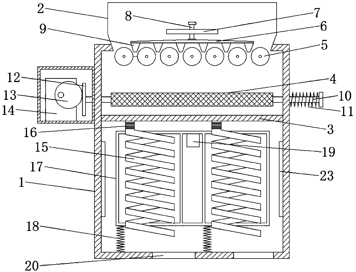
[0018] Please refer to the figure, in the embodiment of the present invention, an agricultural grain spiral falling drying device includes a housing 1, a feed hopper 2, a partition 3 and a hot air pipe 23; the feed hopper 2 is fixedly installed on the housing 1, and communicates with the housing 1, and feeds the incoming grain into the housing 1; the partition 3 is horizontally fixed in the housing 1, and divides the housing 1 into upper and lower parts.

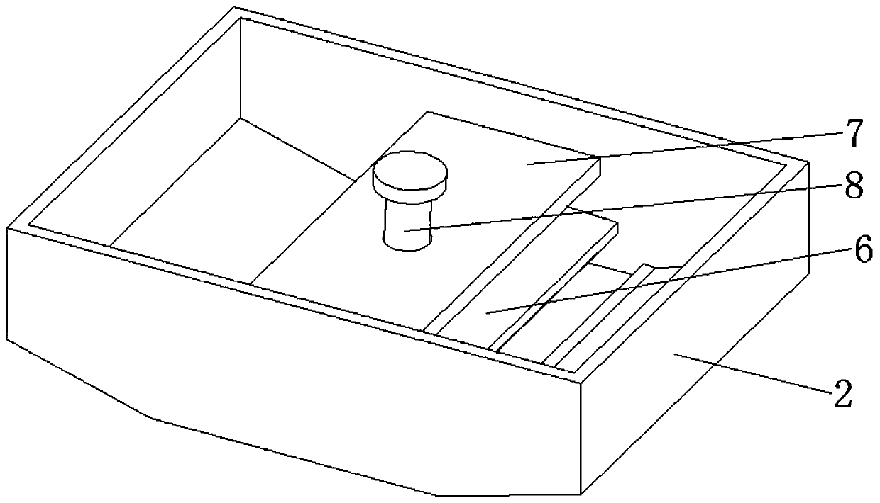
[0019] The connection between the bottom of the feed hopper 2 and the housing 1 is evenly and equidistantly provided with several horizontal retaining rollers 5, and the retaining rollers 5 rotate around the central axis, so that the grains falling from above can pass through the adjacent retaining rollers 5. The gap between them falls to avoid falling more grains at one time; a horizontal liftable baffle 6 is arranged in the feed hopper 2, and the baffle 6 is located above the bottom of the feed hopper 2, and the baffle 6 T...

Embodiment 2

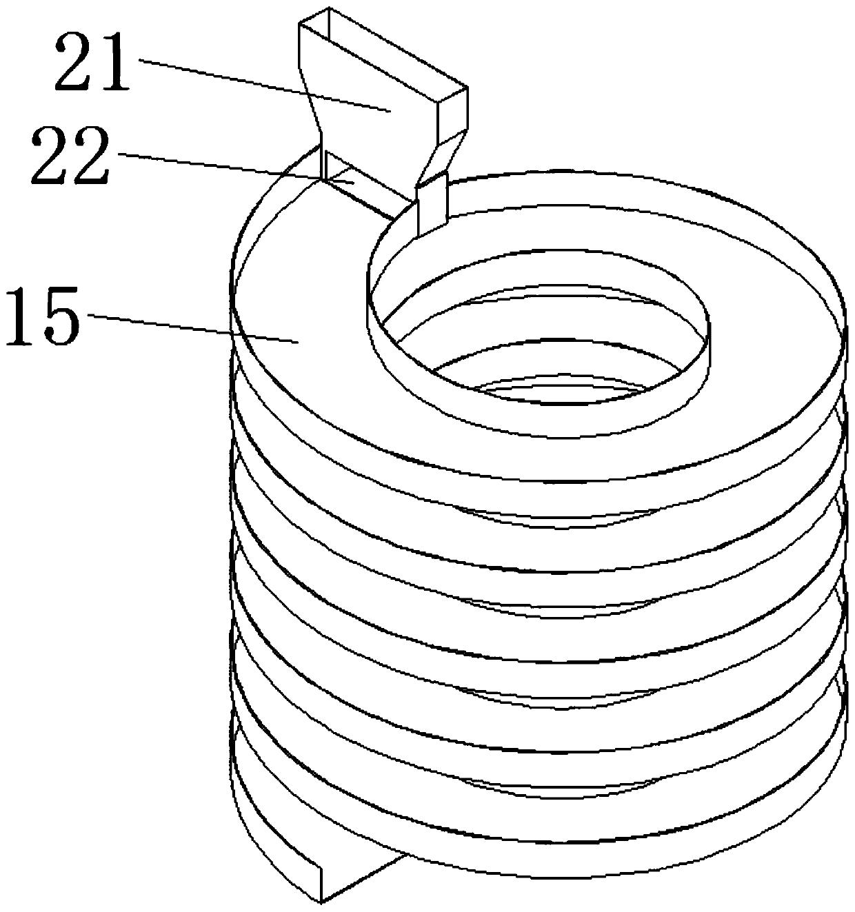
[0023] On the basis of Embodiment 1, a plurality of spiral flow channels 15 are fixedly connected to the same support frame 17, and a plurality of support springs 18 are fixed between the bottom of the support frame 17 and the bottom of the housing 1, and are supported by the support springs 18. Bracing frame 17, vibrating motor 19 is installed on bracing frame 17, drives whole shell supporting frame 17 to shake after vibrating motor 19 starts, is convenient to the whereabouts of the grain in the spiral flow channel 15, improves the fluidity of grain on the spiral flow channel 15.

[0024] When in use, the grain is fed through the feed hopper 2, and under the action of the retaining roller 5 and the retaining block 9, the grain falls between the adjacent retaining rollers 5 to control the feeding speed, and the retaining block 9 can Change the size of the gap to facilitate control and adjustment; the falling grains are dispersed through the horizontal reciprocating deceleration...


PUM


Abstract

The invention relates to the field of agriculture, and in particular, discloses an agricultural cereal spiral falling and drying device. The device comprises a shell, a feed hopper, a separation plateand hot air pipes; multiple horizontal stop rollers are uniformly arranged in the connected place of the bottom of the feed hopper with the shell at equal intervals; a horizontal baffle plate capableof being lifted is arranged in the feed hopper; the baffle plate is positioned above the bottom of the feed hopper; multiple stoppers are fixed on the lower surface of the baffle plate; multiple spiral runners are formed under the separation plate in the vertical direction; and the hot air pipes are arranged on the inner wall of the shell corresponding to the spiral runners. Through arrangement of the stop rollers and the stoppers at the bottom of the feed hopper, the unloading quantity can be controlled, so that cereals uniformly enter the feed hopper without blocking meshes, the load of internal equipment is reduced, and smooth falling of the cereals is guaranteed; and the cereals are fully contacted with hot air in the spiral runners for fully drying, and continuously fall down in thespiral runners for drying without needing stop for unloading.

Description

technical field [0001] The invention relates to the field of agriculture, in particular to a spiral falling drying device for agricultural grains. Background technique [0002] With the deepening of the reform of my country's grain circulation system, the full opening of the grain purchase market, and the diversification of grain purchase entities, in recent years some farmers, grain depots, and grain processing enterprises have equipped themselves with grain dryers to dry them in time after purchasing high-moisture grains. Drying and storage, the use of these dryers has greatly alleviated the problem that grains with high moisture content cannot be purchased and stored in time, reduced the loss of grain mildew, and improved the economic benefits of farmers and enterprises. Although the existing agricultural grain dryer realizes the drying of the grain and makes the grain contact with the hot air through vibration, however, due to the large amount of grain entering at one tim...

Claims


Application Information

Patent Timeline
IPC IPC(8): F26B17/12F26B21/00F26B25/00A23B9/08
CPCA23B9/08F26B17/12F26B21/004F26B25/002F26B2200/06
Inventor 陆璨
Owner 西藏瑞华资本管理有限公司
Learn More