Method for optimizing structure of laminated glass product

A technology of laminated glass and optimization method, applied in the direction of applying repeated force/pulsation force to test the strength of materials, instruments, electrical digital data processing, etc., can solve the problem that the dynamic failure of laminated glass cannot be effectively overcome, and achieve the optimization of structural form and improvement The effect of impact resistance

Active Publication Date: 2019-11-29
BEIJING MECHANICAL EQUIP INST
View PDF8 Cites 1 Cited by
  • Summary
  • Abstract
  • Description
  • Claims
  • Application Information

AI Technical Summary

Problems solved by technology

[0004] In view of the above analysis, the embodiment of the present invention aims to provide a structural optimization method for laminated glass products to solve the problem that the existing technology cannot effectively overcome the dynamic failure of laminated glass

Method used


Image

  • Method for optimizing structure of laminated glass product
  • Method for optimizing structure of laminated glass product
  • Method for optimizing structure of laminated glass product

Examples


Embodiment 1

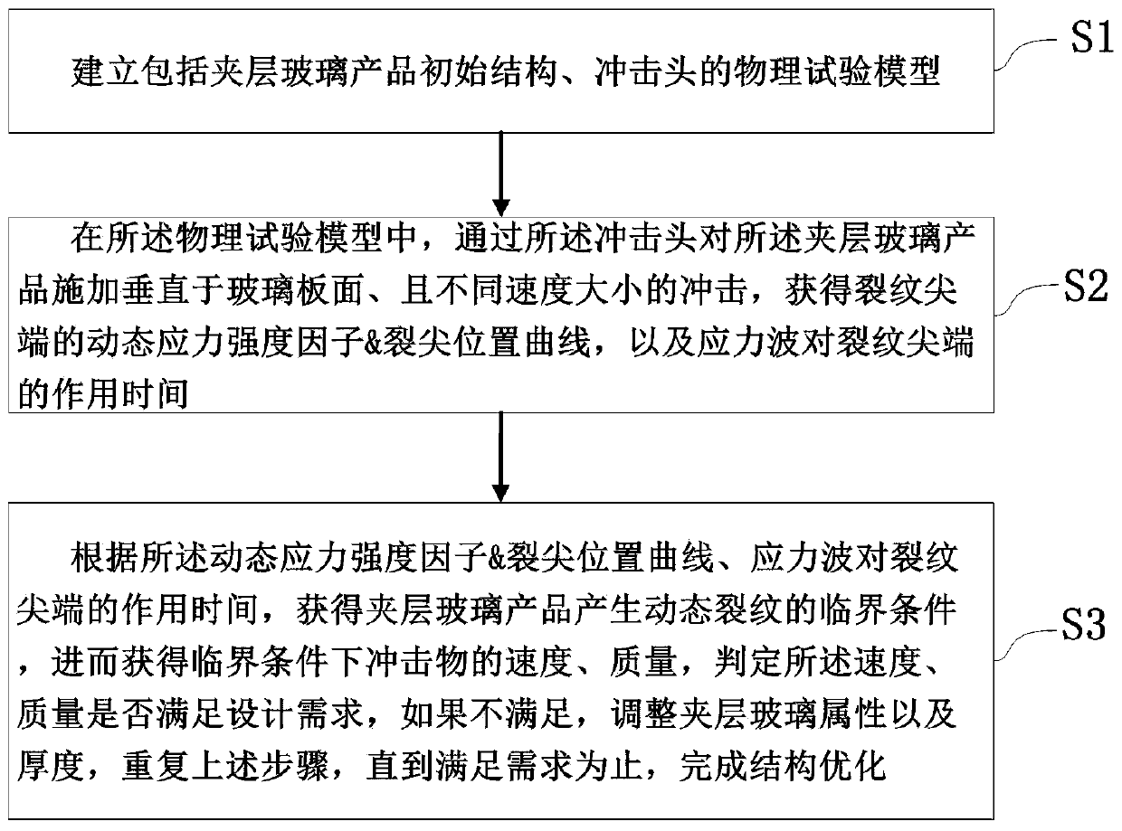
[0069] A specific embodiment of the present invention discloses a method for optimizing the structure of laminated glass products, such as figure 1 shown, including the following steps:

[0070] S1. Establish a physical test model including the initial structure of the laminated glass product and the impact head;

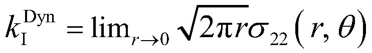
[0071] S2. In the physical test model, apply impacts perpendicular to the glass plate surface and at different speeds to the laminated glass product through the impact head to obtain the dynamic stress intensity factor-crack tip position curve of the crack tip, and The action time of the stress wave on the crack tip;

[0072] S3. According to the dynamic stress intensity factor-crack tip position curve and the action time of the stress wave on the crack tip, obtain the critical condition for the generation of dynamic cracks in laminated glass products, and then obtain the speed and quality of the impacting object under the critical condition, and determine the Whe...

Embodiment 2

[0075] Optimizing on the basis of the structure optimization method of the laminated glass product in Embodiment 1, the step S1 can be further refined into the following steps:

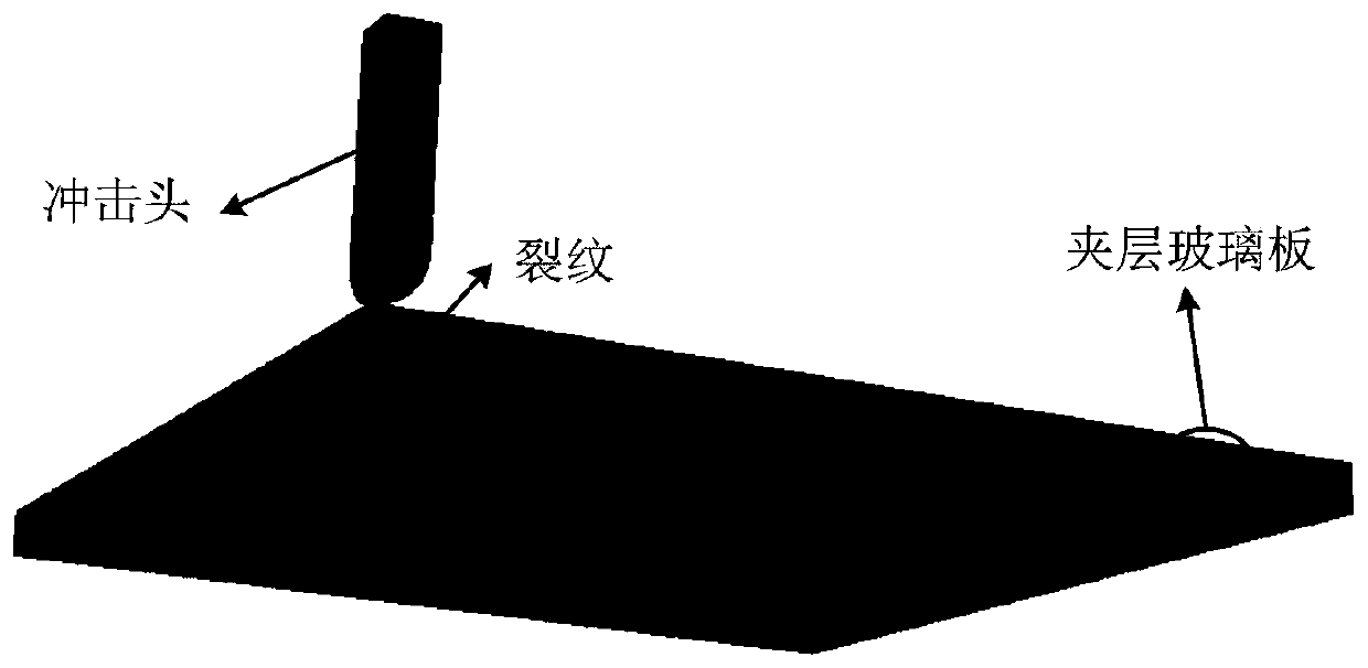
[0076] S11. Obtain the dimensions and material parameters of the initial structure of the laminated glass product, and establish an initial simulation model of the laminated glass product, such as figure 2 shown;

[0077] S12. At a preset position above the laminated glass of the laminated glass product, establish an impact head simulation model to ensure that the impact direction is perpendicular to the surface of the laminated glass;

[0078] S13. Set the impact space, establish the physical test model including the initial simulation model of the laminated glass product, the impact head simulation model, and the impact space, divide the grid, and ensure that the two glass layers and the middle layer of the laminated glass are respectively provided with at least three layers of mesh grid unit to c...


PUM


Abstract

The invention relates to a method for optimizing a structure of a laminated glass product, belongs to the technical field of laminated glass and solves the problem in the prior art that the dynamic failure of laminated glass cannot be effectively overcome. The method comprises the following steps of establishing a physical test model including an initial structure of a laminated glass product andan impact head; applying impacts of different speeds perpendicular to the glass plate surface to the laminated glass product through the impact head to obtain a dynamic stress intensity factor-crack tip position curve at the crack tip, and an action time of the stress wave on the crack tip; obtaining a critical conditions for dynamic cracks of the laminated glass product according to the curve andthe action time of the stress wave on the crack tip so as to obtain the speed and quality of the impact object under the critical conditions, determining whether the speed and quality meet the designrequirements, adjusting the properties and thickness of the laminated glass if not, repeating the above steps until the requirements are met, and completing the structural optimization.

Description

technical field [0001] The invention relates to the technical field of laminated glass, in particular to a method for optimizing the structure of a laminated glass product. Background technique [0002] Laminated glass products are special laminate structures formed by hard and brittle glass materials and soft and tough interlayer polymer materials through high temperature and high pressure. Due to its excellent light transmission, formability and impact resistance, laminated glass has great potential as a transparent protective material, and has been widely used in automobile windshield glass and architectural curtain wall glass. [0003] Under the action of external impact, micro-cracks will be generated in the laminated glass, which will gradually extend and eventually lead to the failure of the laminated glass. In order to utilize laminated glass as a transparent protective material more effectively, it is necessary to comprehensively study its crack propagation behavio...

Claims


Application Information

Patent Timeline
Patent Type & Authority Applications(China)
IPC IPC(8): G01N3/32G06F17/50
CPCG01N3/32G01N2203/001G01N2203/0064G01N2203/0066G01N2203/0218
Inventor 徐晓庆董彦鹏
Owner BEIJING MECHANICAL EQUIP INST
Why Eureka
Try Eureka