Steel billet positioning method based on machine vision camera image processing and application

A machine vision and image processing technology, applied in image data processing, image enhancement, image analysis, etc., can solve the problems of limited analog cameras, fragile optical devices, and no learning ability, so as to improve accuracy and real-time performance, and optimize steel billets Positioning algorithm, the effect of reducing the labor load of workers

Pending Publication Date: 2019-11-29
武汉西尔塔信息技术有限公司
View PDF0 Cites 23 Cited by
  • Summary
  • Abstract
  • Description
  • Claims
  • Application Information

AI Technical Summary

Problems solved by technology

Disadvantages: 1. Narrow deployment scope
The directionality of the laser is too strong, so it must be installed at the front of the inspection object, and other positions cannot be measured, which greatly limits its application; 2. The optical device is very fragile, and generally requires a very complicated shell for protection, and at the same time, it cannot be used for close-up measurement of high-temperature steel billets , unable to take advantage of the high precision of laser ranging. 3. Optical materials are very sensitive to temperature, and the measurement error caused by temperature drift is very large; Summary: Laser ranging positioning is only used in some cases where the accuracy is extremely high and the working conditions are excellent.
2. Contact positioning, advantages: the best anti-interference; Disadvantages: 1. Contact measurement, high-temperature objects have serious heat conduction, and the detection equipment is easily damaged and basically unusable. The equipment is easily displaced by the impact of the billet, and the measurement error is large; summary: contact positioning has been completely eliminated at this stage
[0003] In image processing and positioning methods, the following two camera devices are commonly used now; 1. Analog camera, which is a traditional coaxial camera. The acquisition link includes two parts: an analog camera and an image acquisition card. Advantages: high real-time performance; Disadvantages: 1. The precision is low, the analog camera is limited by the bandwidth of the coaxial cable, the highest resolution is not more than 800x600, it cannot be used in high-precision occasions, 2. The distance is short
The use of network cables can ensure stable transmission within 100 meters, and relays can be added for further distances. 3. Strong anti-interference ability, digital transmission avoids the problem that analog signal transmission is easily interfered; Disadvantages: 1. Poor real-time performance, compared to analog cameras driven by PC The way the image acquisition card collects images, the video camera encodes the images on the camera side, and transmits the compressed (generally H.264) images to the image processing PC through Ethernet, and the transmission delay reaches the second level. It is unavailable in high-real-time occasions. 2. Information loss. In order to ensure that the bandwidth usage rate is as low as possible, video cameras generally use H.264, H.265 and other video encoding methods to encode images, resulting in image edges, The key positioning information such as corner points is lost, and these are the data necessary to ensure the positioning accuracy of the billet
[0005] Most of the existing image processing methods for detecting the position of the slab have the following problems: 1. No state memory, high error rate
Now the industrial site has higher and higher requirements for the detection accuracy of the billet position, and the camera resolution is constantly pushed up. The real-time performance of the algorithm based entirely on edge recognition is getting worse and worse. 3. No learning ability and poor scalability
The core idea of ​​the traditional image processing algorithm is to analyze and judge the position of the slab through the preset image features. When the surrounding environment changes or the shape of the slab changes, the corresponding image features will also change, and the preset feature value is used to When doing analysis, misjudgment will occur, and the expansion ability is very poor; for this reason, the present invention proposes a billet positioning method based on machine vision camera image processing and its application

Method used


Image

  • Steel billet positioning method based on machine vision camera image processing and application

Examples


Embodiment Construction

[0044] In order to make the technical means, creative features, goals and effects achieved by the present invention easy to understand, the present invention will be further described below in conjunction with specific embodiments.

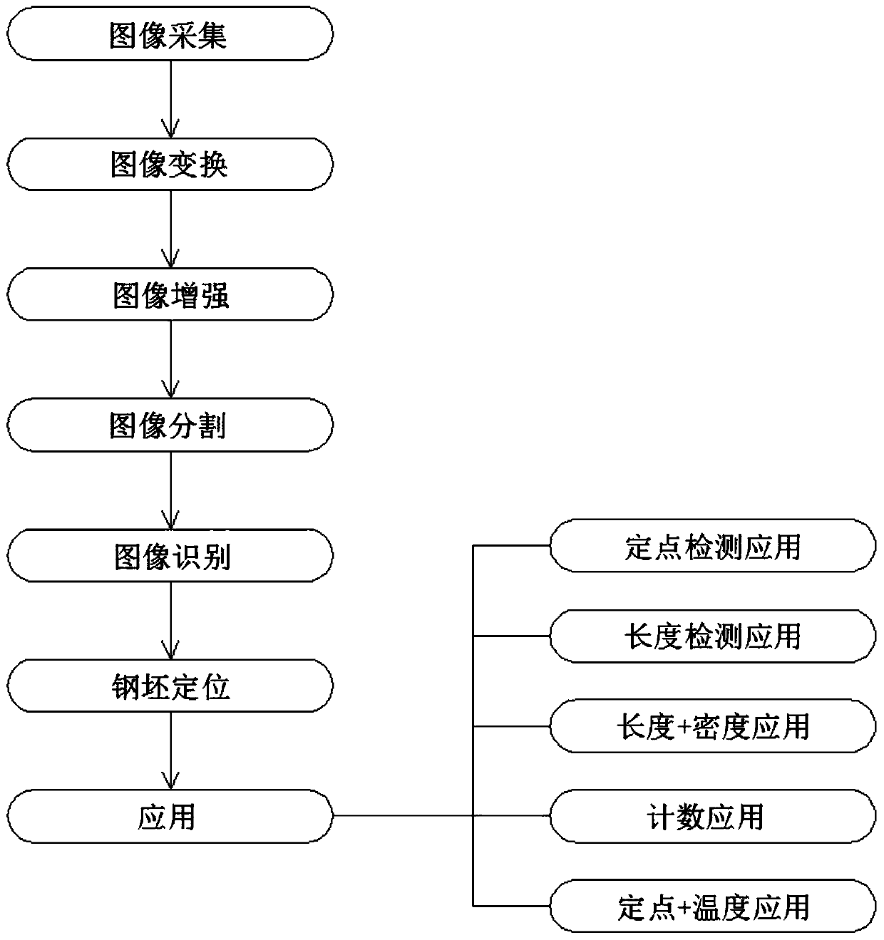
[0045] see figure 1 , the present invention provides a technical solution: a billet positioning method and application based on machine vision camera image processing, comprising the following steps:

[0046] Step 1: Image acquisition; use the machine vision camera to collect images, the machine vision camera has the following characteristics:

[0047] ①: The performance of the machine vision camera is stable and reliable, easy to install, the camera is compact and strong, not easy to damage, and has a long continuous working time, which can be used continuously for a long time in a poor environment;

[0048] ②: The shutter time of the machine vision camera is very short, and it can capture high-speed moving objects. Common cameras generally have...


PUM


Abstract

The invention provides a steel billet positioning method based on machine vision camera image processing and application. The steel billet positioning method comprises the following steps of image acquisition, image transformation, image enhancement, image segmentation, image recognition, steel billet positioning and application. The steel billet positioning method based on machine vision camera image processing and the application design are reasonable, the machine vision camera is used for image acquisition, the steel billet positioning algorithm is optimized, the use surface of deep-diggingsteel billet positioning is improved, a novel steel billet positioning system which is high in precision, high in real-time performance and convenient to install is achieved, the application range iswide, and the steel billet positioning method is suitable for large-scale popularization.

Description

technical field [0001] The invention belongs to the technical field of steel billet positioning on the industrial site in the metallurgical industry, and in particular relates to a steel billet positioning method based on machine vision camera image processing and its application. Background technique [0002] Various billet measurement and positioning technologies have been widely used in industrial sites, especially in the metallurgical industry. The demand for billet positioning is showing a trend of wider range and higher precision. The existing billet object positioning technology can basically be classified as Classified into the following three types: 1. Laser distance measurement and positioning. Advantages: 1. Non-contact, easier to install and deploy than contact measurement; 2. High accuracy in close-range measurement. Disadvantages: 1. Narrow deployment scope. The directionality of the laser is too strong, so it must be installed at the front of the inspection o...

Claims


Application Information

Patent Timeline
Patent Type & Authority Applications(China)
IPC IPC(8): G06T7/73G01B11/00G01B11/02G01B11/28G01N21/88
CPCG06T7/73G01B11/00G01B11/02G01B11/285G01N21/8851G06T2207/10016G06T2207/10024G06T2207/20061G06T2207/30108G01N2021/8887
Inventor 王喜帅红郑超国
Owner 武汉西尔塔信息技术有限公司
Why Eureka
Try Eureka