Single-side hub motor based on power generation tire

A hub motor and tire technology, applied to synchronous motors with stationary armatures and rotating magnets, motors, tire parts, etc., can solve problems such as slow process, reduced battery power storage capacity, and influence on consumers' car purchase choices. Achieve the effects of reducing power loss, facilitating maintenance and replacement, and saving storage links

Inactive Publication Date: 2019-11-29
李永红
View PDF0 Cites 0 Cited by
  • Summary
  • Abstract
  • Description
  • Claims
  • Application Information

AI Technical Summary

Problems solved by technology

Although national policies actively promote the development of new energy vehicles, the market performance of new energy vehicles is not good
The biggest obstacle restricting the development of new energy vehicles is the endurance problem caused by the current underdeveloped battery technology, as well as the long charging time of pure electric vehicles and the lack of charging piles, which also seriously affect consumers' car purchase choices
What's more deadly is that the storage capacity of batteries drops sharply in winter, and the cruising range is seriously reduced, which makes new energy vehicles not accepted by consumers.
[0003] Although major car companies and scientific research institutions are actively researching battery technology, energy-saving technology, vehicle energy recovery technology, and charging technology, and the country is also stepping up the deployment of infrastructure such as charging piles, the results are minimal and the progress is slow. Effectively solve the main problems in the development of new energy vehicles. Therefore, a new type of vehicle energy recovery and energy saving device needs to be studied urgently

Method used


Image

  • Single-side hub motor based on power generation tire
  • Single-side hub motor based on power generation tire

Examples


Embodiment Construction

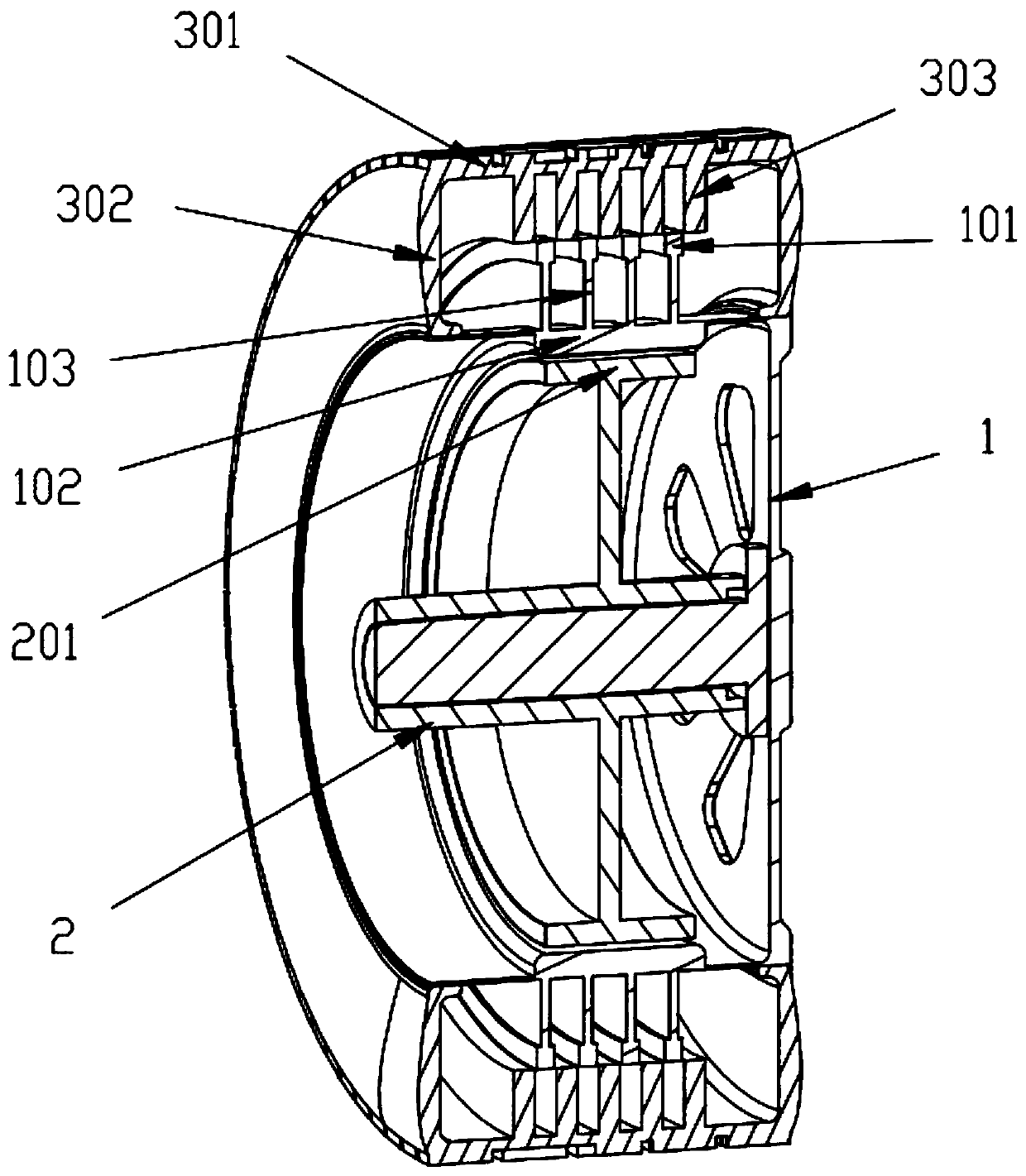
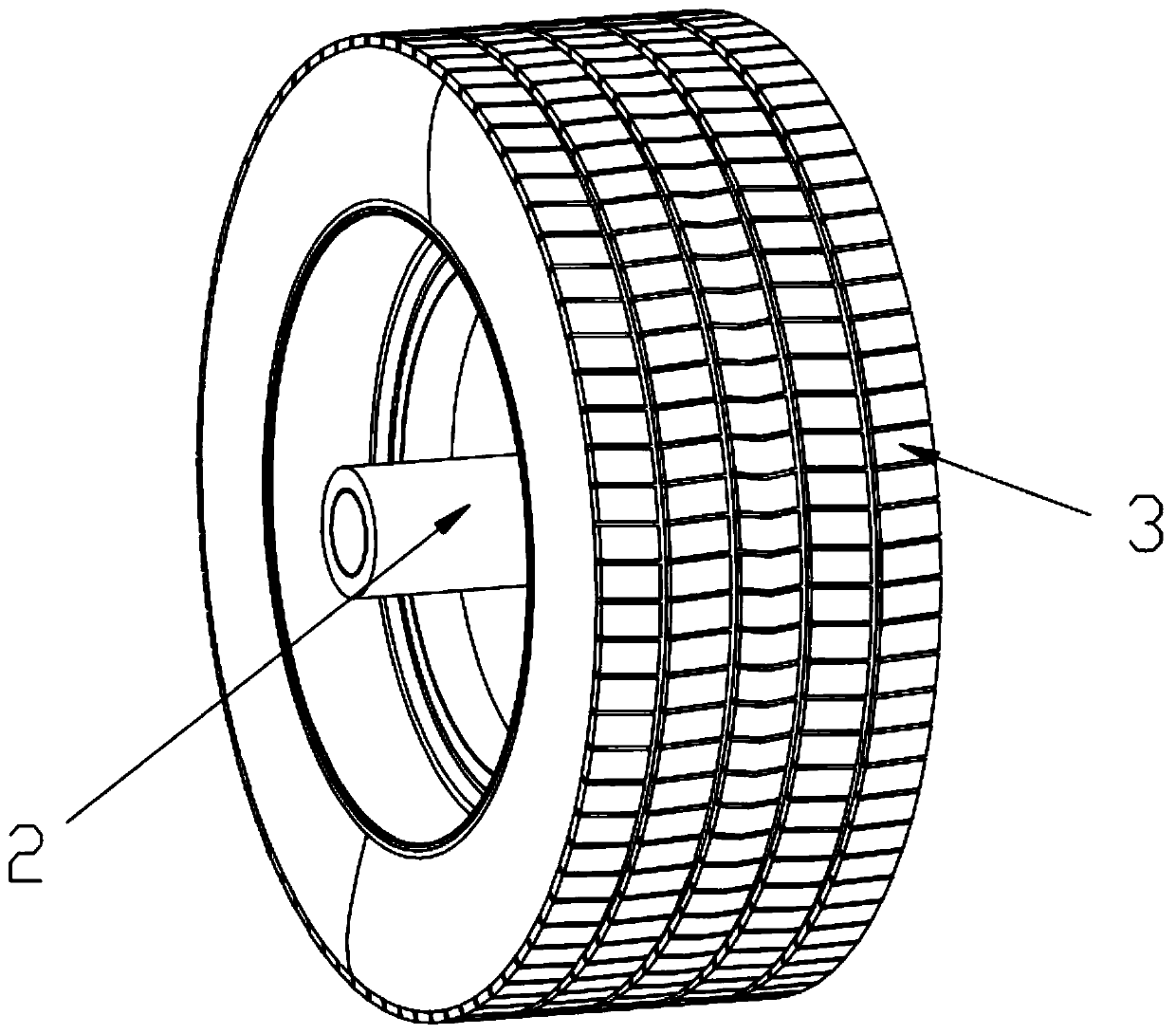
[0014] With reference to the accompanying drawings, a unilateral hub motor based on power generation tires includes a hub 1, a hub motor 2 arranged on one side of the hub 1, and a tire 3 arranged on the outer ring of the hub 1. The hub motor 2 does not rotate with the hub 1 Turning, the tire 3 is a hollow structure, and the tire 3 includes an upper tire surface 301 opposite to the outer surface of the outer ring of the wheel hub 1 and a side tire surface 302 arranged on both sides of the upper tire 301 surface and socketed with the wheel hub 1. The inner side of the upper tire surface 301 is provided with permanent magnets 303 along the inner wall of the upper tire surface 301. The number of the permanent magnets 303 is multiple, and the permanent magnets 303 are arranged at intervals along the width direction of the inner side of the upper tire surface 301. A plurality of sets of copper coils 101 are arranged on the outer surface of the ring, and the gaps between the copper co...


PUM


Abstract

The invention discloses a single-side hub motor based on a power generation tire. The motor comprises a wheel hub, a wheel hub motor arranged on one side of the wheel hub and a tire arranged on the outer side of the wheel hub. Permanent magnets are arranged on the inner side of the upper tire tread along the inner wall of the upper tire tread; the permanent magnets are arranged at intervals in thewidth direction of the inner side of the upper tire tread; a plurality of groups of copper coils are arranged on the outer side surface of the hub outer ring; gaps between the copper coils and the permanent magnets are correspondingly arranged; a motor rotor winding connected with the copper coils is arranged on the inner side surface of the hub outer ring; a motor stator permanent magnet corresponding to the motor rotor winding is arranged at the outer edge of the hub motor. According to the invention, through the arrangement of the permanent magnets and the copper coils, the tire deformation generated by vehicle weight is used for generating power, and the generated electric energy is directly converted into mechanical energy of the tire through the novel hub motor, thereby saving a storage link, and greatly reducing the electric energy loss. The electric energy generated by the power generation mode can also be stored in a storage battery to be used by a vehicle.

Description

technical field [0001] The invention relates to the technical field of in-wheel motors, in particular to a unilateral in-wheel motor based on power generation tires. Background technique [0002] In recent years, new energy vehicles have developed rapidly, and various models have emerged in an endless stream. Although national policies actively promote the development of new energy vehicles, the market performance of new energy vehicles is not good. The biggest obstacle restricting the development of new energy vehicles is the endurance problem caused by the current underdeveloped battery technology, as well as the long charging time of pure electric vehicles and the lack of charging piles, which also seriously affect consumers' car purchase choices. What's more deadly is that the battery's power storage capacity drops sharply in winter, and the cruising range is severely reduced, which makes new energy vehicles not accepted by consumers. [0003] Although major car compan...

Claims


Application Information

Patent Timeline
IPC IPC(8): H02K21/24B60C19/00
CPCB60C19/00B60C2019/005H02K21/24Y02T10/64
Inventor 李永红
Owner 李永红
Why Eureka
Try Eureka