Supercharge Your Innovation With Domain-Expert AI Agents!

Power tool

A technology of power tools and power parts, which is applied in the direction of manufacturing tools, metal processing equipment, portable motorized devices, etc., and can solve problems such as carbon brush wear

Active Publication Date: 2019-11-29
NITTO KOHKI CO LTD
View PDF9 Cites 0 Cited by
  • Summary
  • Abstract
  • Description
  • Claims
  • Application Information

AI Technical Summary

Problems solved by technology

Generally, in a commutator motor, carbon brushes are brought into contact with a commutator that rotates together with the rotor to supply current to the rotor, but the carbon brushes are gradually worn due to friction with the rotating commutator, and therefore need to be replaced periodically

Method used


Image

  • Power tool
  • Power tool
  • Power tool

Examples


Embodiment Construction

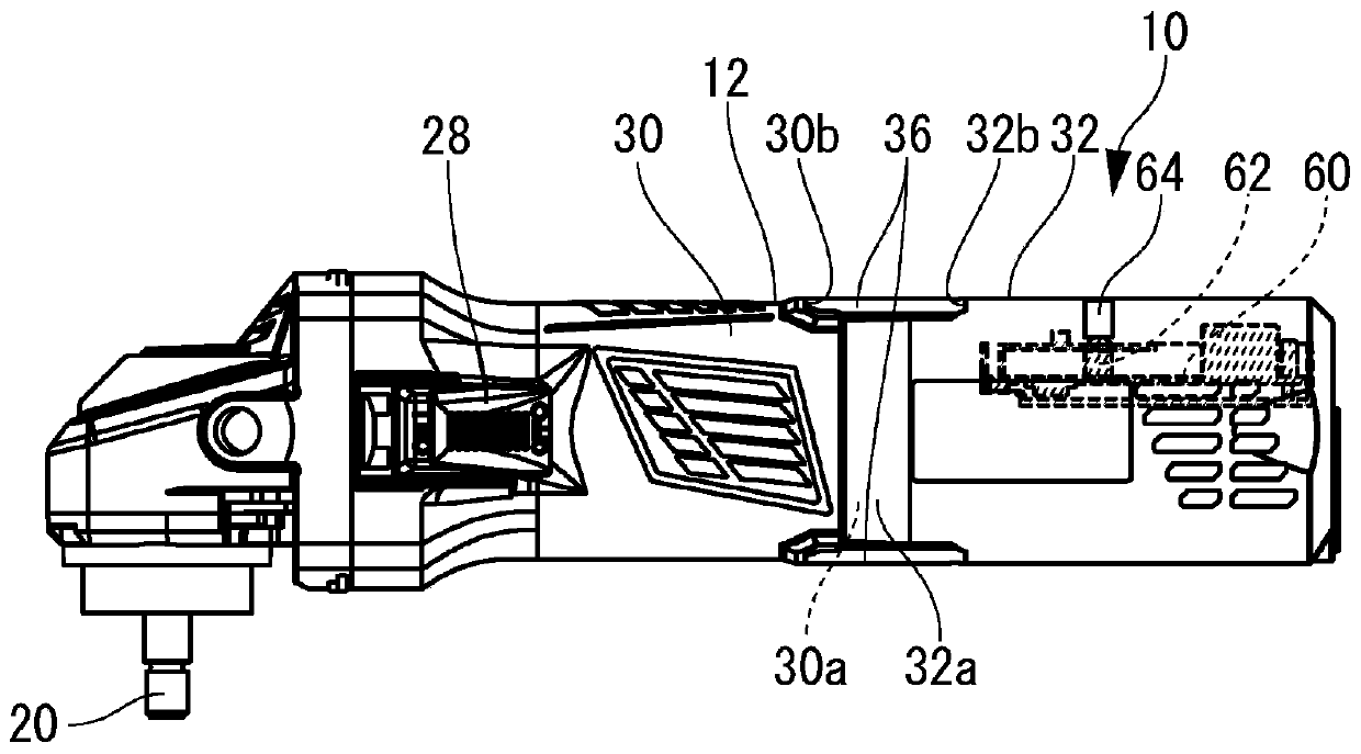
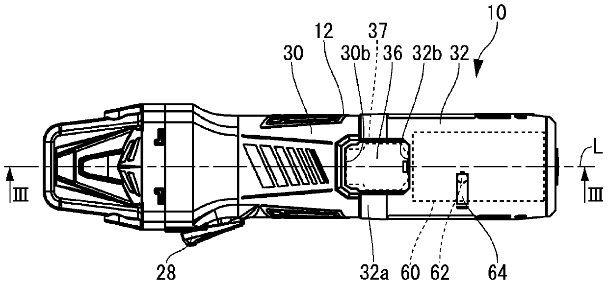
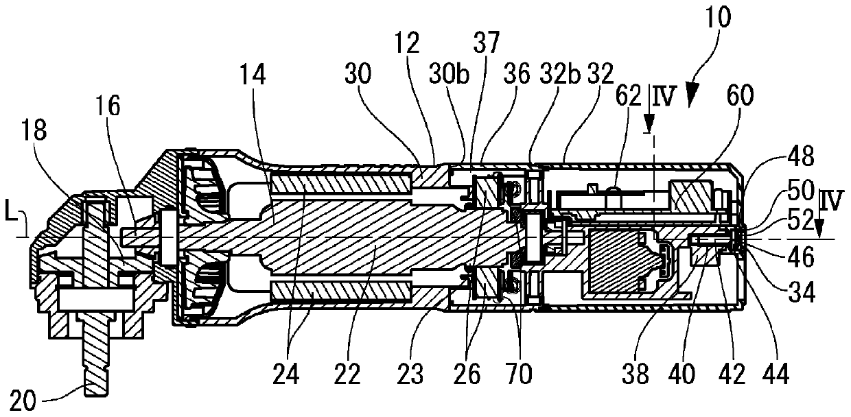
[0043] Such as Figure 1 to Figure 3 As shown, a power tool 10 according to an embodiment of the present invention is an electric power tool including a commutator motor 14 as a power part in a casing 12 . On the tool output shaft 20 drivingly coupled to the rotation output shaft 16 of the commutator motor 14 via the bevel gear 18, necessary members such as a disc-shaped polishing pad are attached according to the application.

[0044] Such as image 3 As shown, the commutator motor 14 has: a rotor 22, which is installed to be rotatable relative to the housing 12; a stator 24, which is arranged around the rotor 22 and fixed to the housing 12; Contact with the commutator 23 of the rotor 22. A switch 28 is attached to the casing 12 , and driving of the commutator motor 14 is started / stopped by operating the switch 28 . The brushes 26 slide against the high-speed rotating commutator 23 and thus gradually wear out. Therefore, after using the power tool 10 for a certain period ...


PUM


Abstract

The purpose of the present invention is to provide a power tool that can make access to the interior of a housing easier and safer to perform. The present invention is a power tool (10) provided witha commutator motor (14) in a housing (12), wherein the housing (12) has a first housing unit (30), a second housing unit (32) that can move with respect to the first housing unit (30), a tapping screw(34) that fixes these, and a cover (36) that is attached by being sandwiched between the first housing unit (30) and the second housing unit (32). When the tapping screw (34) is loosened, the tappingscrew (34) engages with an engaging ring (50) of the second housing unit (32) by being displaced in a direction away from the first housing unit (30) and displaces the second housing unit (32) in theaway direction. In this manner, the cover (36) is in a removable state. In addition, when the tapping screw (34) is tightened, a state in which the cover (36) is attached is restored by the second housing unit (32) being displaced in a direction toward the first housing unit (30) by the tapping screw (34).

Description

technical field [0001] The present invention relates to a power tool including a power unit inside a housing. Background technique [0002] In a power tool including a power unit in a housing, an operator usually performs maintenance on the power unit and the like arranged in the housing by disassembling the housing. For example, Patent Document 1 discloses a grinder including a commutator motor as a power unit in a housing including a motor housing and a rear cover. Generally, in a commutator motor, carbon brushes are brought into contact with a commutator that rotates together with the rotor to supply current to the rotor. However, the carbon brushes are gradually worn due to friction with the rotating commutator, and therefore need to be replaced periodically. In this grinder, the back cover is removed by removing the fixing screws that fix the back cover to the motor housing, and then the carbon brushes are replaced. [0003] prior art literature [0004] patent docum...

Claims


Application Information

Patent Timeline
IPC IPC(8): B25F5/02B25F5/00B24B23/02
CPCB25F5/02B24B23/028B24B23/02B25F5/00
Inventor 宫城贵则清水裕之远藤大辅
Owner NITTO KOHKI CO LTD
Features
  • R&D
  • Intellectual Property
  • Life Sciences
  • Materials
  • Tech Scout
  • Unparalleled Data Quality
  • Higher Quality Content
  • 60% Fewer Hallucinations
Learn More