Aerospace-grade ball grid precision machining system
A precision machining and aerospace-level technology, applied in the direction of metal processing equipment, metal processing machinery parts, manufacturing tools, etc., can solve the problems of interactive active parts that have not been seen in the application, and achieve the purpose of providing space processing range, improving processing efficiency, and processing smooth process effect
- Summary
- Abstract
- Description
- Claims
- Application Information
AI Technical Summary
Problems solved by technology
Method used
Image

Examples
Embodiment 1
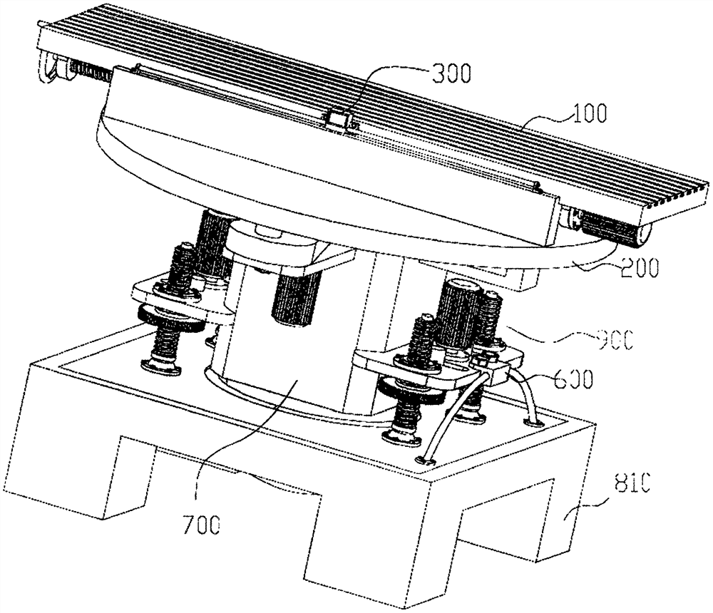
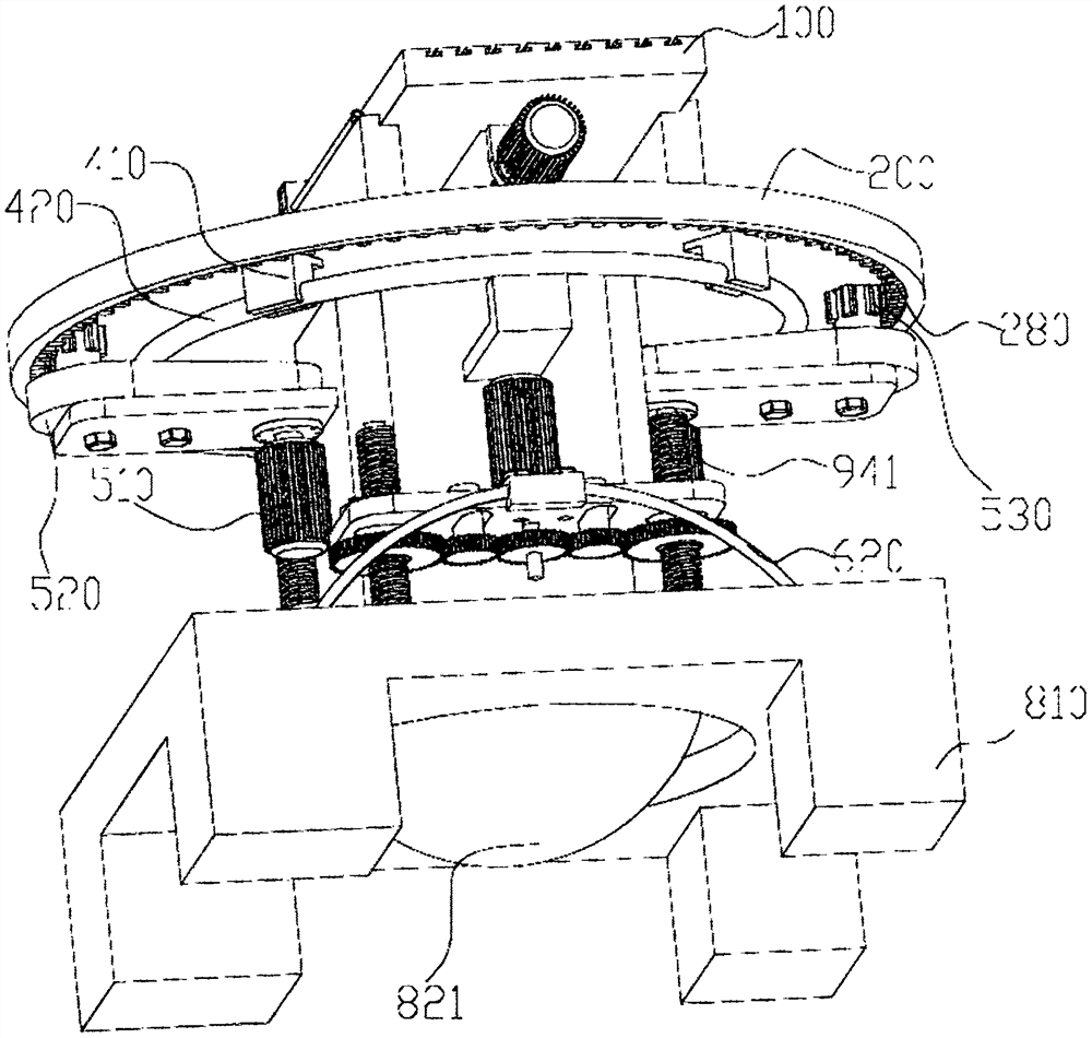
[0050] The invention provides an aerospace-grade ball grid precision machining system, such as Figure 1-11 As shown, it includes a workbench 100, a rotary table 200, a linear displacement ball grid 300, a first angular displacement ball grid 400, an anti-backlash transmission system 500, a second angular displacement ball grid 600, a swing seat 700, a universal ball seat 800 and The swing assembly 900, the worktable 100 is moved and set on the rotary table 200, the linear displacement ball grid 300 measures the movement of the worktable 100, the rotary table 200 is rotated and set on the swing seat 700 through the anti-backlash transmission system 500, the first angular displacement ball The grid 400 measures the amount of rotation of the rotary table 200, the swing seat 700 is set on the universal ball seat 800 through the swing assembly 900, the second angular displacement ball grid 600 measures the swing amount of the swing seat 700, and the workpiece is fixed on the workbe...
Embodiment 2
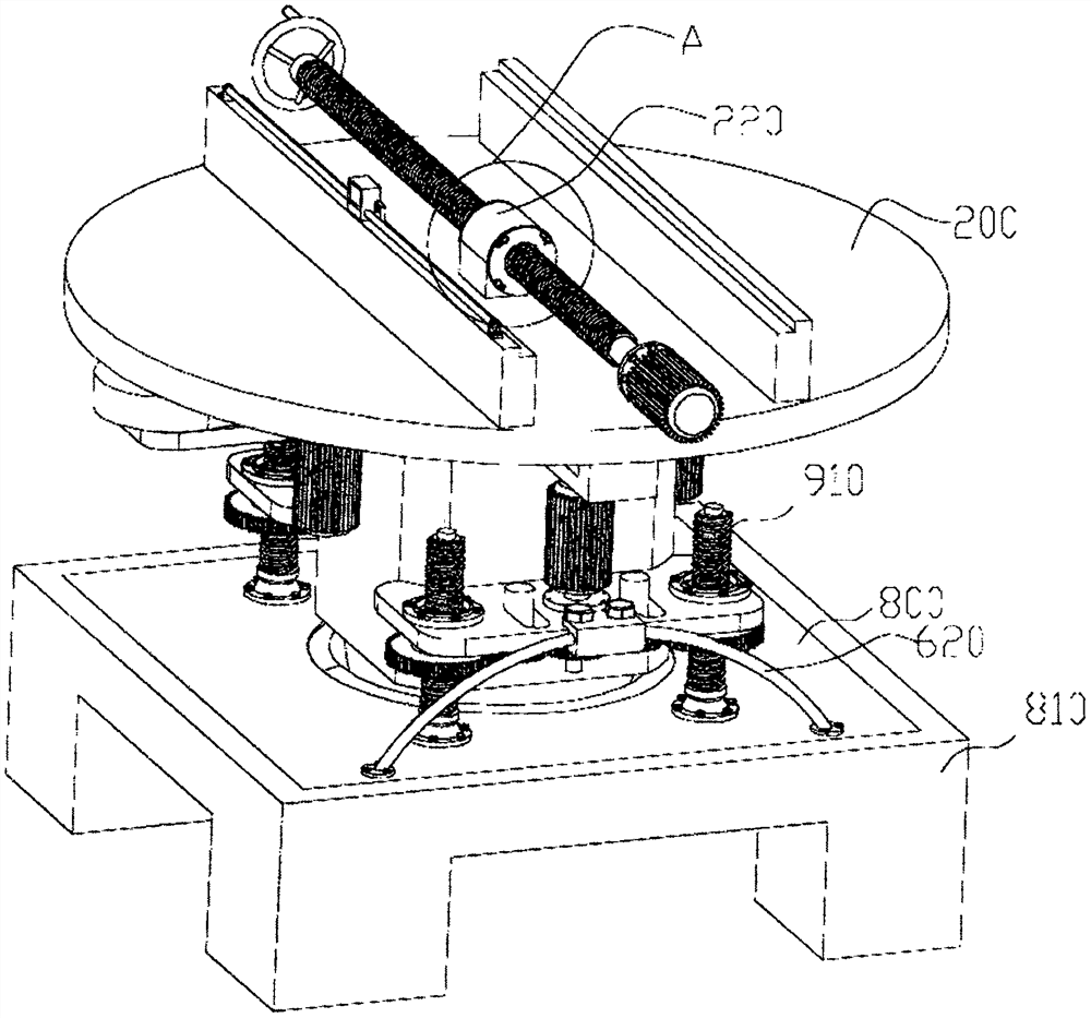
[0067] On the basis of Example 1, as Figure 3-5 As shown, the backlash-free screw base 260 is divided into a first screw base 261 and a second screw base 262 according to the center, and several waist-shaped holes are opened on the outside of the first screw base 261 and the second screw base 262 263, the first screw seat 261 and the second screw seat 262 are installed on both sides of the screw seat hole 220 through the waist hole 263 through the nut, and after screwing the screw mandrel 230 into the gapless screw seat 260, The installation position of the screw-in screw 230 and the gap-free screw seat 260 is precisely adjusted. Usually, there is a gap between the screw-in screw 230 and the gap-free screw seat 260 that is threaded, and the screw-in screw 230 and the gap-free screw seat 260 The threaded side wall on one side of the backlash-free screw seat 260 is in contact, and the screw-in screw 230 is dragged to move in one direction. When the screw-in screw 230 moves in t...
Embodiment 3
[0069] On the basis of Example 2, such as Figure 9-11 As shown, according to the surface characteristics of the workpiece, in order to control the inclination process of the oscillating seat 700 according to the command, select the speed regulating gear 930 with a suitable pitch circle diameter, adjust the meshing state with the floating screw gear 920 and the power gear 940, Simultaneously, the matching mobile installation shaft 931 is positioned in the elongated through hole 731, so that the speed regulating gear 930 of corresponding size is installed in the swing assembly, and the speed regulating gear 930 is connected with the floating screw gear 920 and the power gear 940. Simultaneous meshing, specifically, if the curved surface of the workpiece has a small radian, increase the diameter of the speed regulating gear 930 to reduce the progress of the swing seat 700 and improve the machining accuracy of the curved surface; if the curved surface of the workpiece has a large ...
PUM
 Abstract
Description
Claims
Application Information