
Grinding main shaft for crystal silicon rough grinding and fine grinding integrated machine and using method thereof

A technology of integrated machine and spindle, which is applied in the direction of grinding drive device, grinding machine tool parts, grinding/polishing equipment, etc., to achieve the effect of reducing floor space, facilitating layout, and small fine grinding allowance

Pending Publication Date: 2019-12-03
QINGDAO GAOCE TECH CO LTD
View PDF0 Cites 4 Cited by
  • Summary
  • Abstract
  • Description
  • Claims
  • Application Information

AI Technical Summary

Problems solved by technology

[0002] Before the slicing process of crystalline silicon, it is necessary to perform grinding, polishing and chamfering on the squared single crystal silicon rod. Usually, a grinding wheel (coarse grinding wheel or fine grinding wheel) is installed on the spindle unit of the grinding head, which will inevitably lead to the deformation of the silicon rod. Rough grinding and fine grinding are not at the same position. Due to the change of processing position, a larger fine grinding allowance is required to ensure the processing of the workpiece when fine grinding silicon rods. How to reduce the grinding allowance and make the wafer more efficient and energy-saving Grinding silicon is a problem we need to solve

Method used


Image

  • Grinding main shaft for crystal silicon rough grinding and fine grinding integrated machine and using method thereof
  • Grinding main shaft for crystal silicon rough grinding and fine grinding integrated machine and using method thereof

Examples


Embodiment Construction

[0024] In order to make those skilled in the art better understand the technical solution of the present invention, the technical solution of the present invention is clearly and completely described below in conjunction with the accompanying drawings of the present invention. Based on the embodiments in this application, those of ordinary skill in the art will Other similar embodiments obtained without creative work shall all fall within the scope of protection of this application. In addition, the directional words mentioned in the following embodiments, such as "upper", "lower", "left", "right", etc., are only referring to the directions of the drawings, therefore, the directional words used are for illustration rather than limitation invent.

[0025] The present invention will be further described below in conjunction with the accompanying drawings and preferred embodiments.

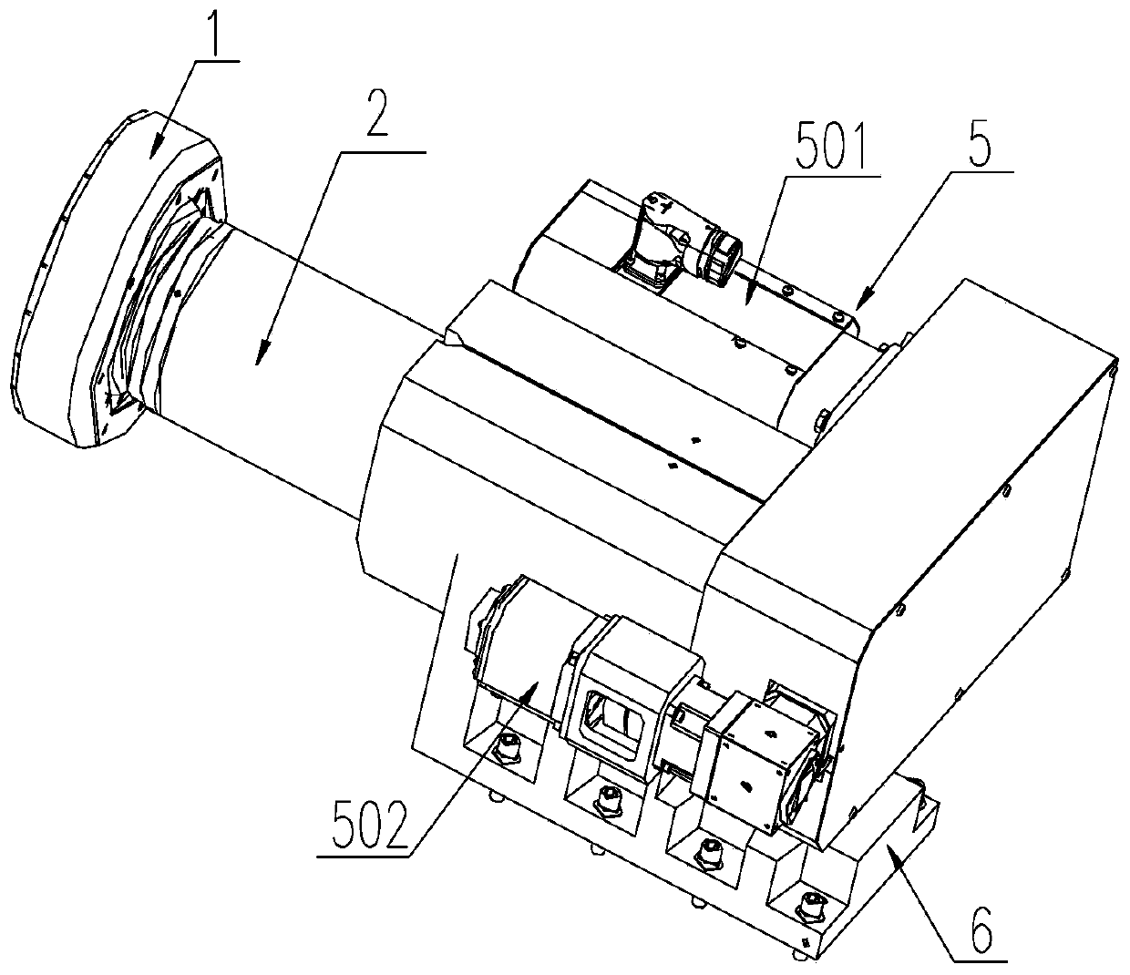
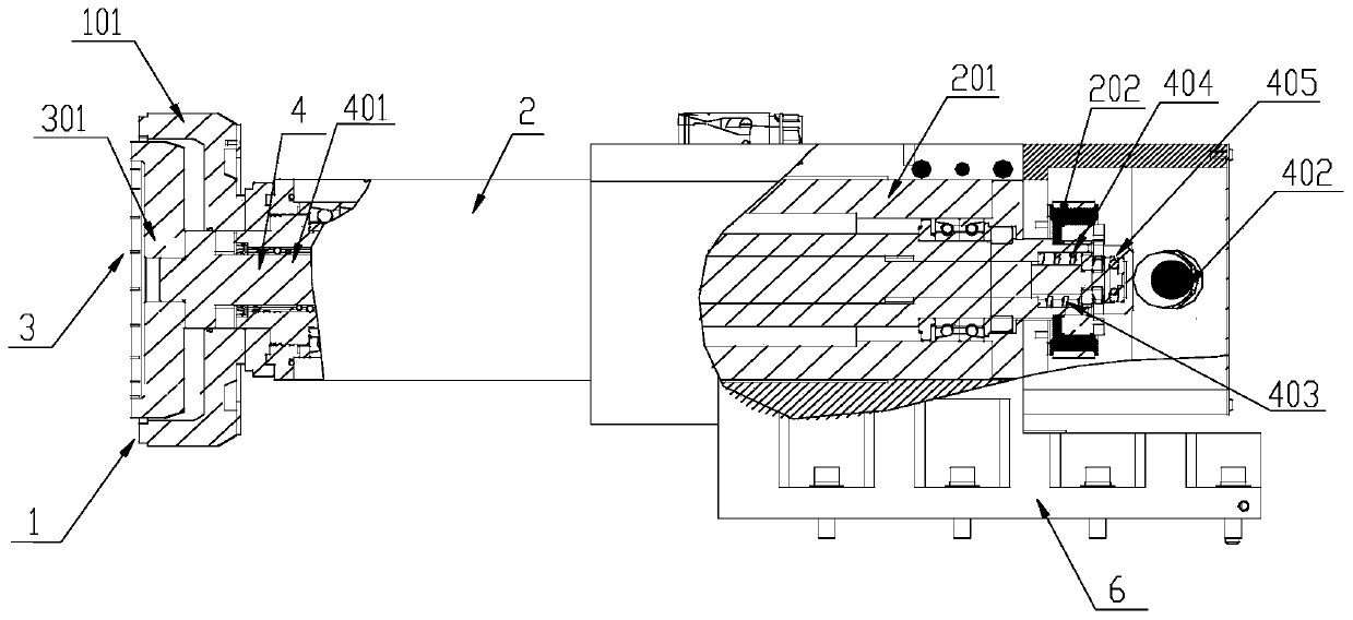
[0026] refer to Figure 1-2 , a grinding spindle for a crystal silicon rough grinding and fine ...


PUM


Abstract

The invention relates to a grinding main shaft for a crystal silicon rough grinding and fine grinding integrated machine and a using method of the grinding main shaft. The invention belongs to the technical field of crystal silicon processing equipment. The integrated machine comprises a rough grinding main shaft mechanism and a fine grinding main shaft mechanism, the rough grinding main shaft mechanism comprises a rough grinding head assembly and a rough grinding main shaft assembly connected with the rough grinding head assembly. The fine grinding main shaft mechanism comprises a fine grinding head assembly and a fine grinding main shaft assembly connected with the fine grinding head assembly. The fine grinding main shaft mechanism is sleeved with the rough grinding main shaft mechanismand connected with a driving assembly, is used for conducting rough grinding and fine grinding on the crystal silicon, can conduct rough grinding and fine grinding machining at the same position of the crystal silicon, can reduce the fine grinding machining allowance, thus greatly improving the efficiency and providing wide market prospects.

Description

technical field [0001] The invention belongs to the technical field of crystal silicon processing equipment, and in particular relates to a grinding spindle used for a crystal silicon rough grinding and fine grinding integrated machine and a using method thereof. Background technique [0002] Before the slicing process of crystalline silicon, it is necessary to perform grinding, polishing and chamfering on the squared single crystal silicon rods. Usually, a grinding wheel (rough grinding wheel or fine grinding wheel) is installed on the spindle unit of the grinding head, which will inevitably lead to the deformation of the silicon rods. Rough grinding and fine grinding are not at the same position. Due to the change of processing position, a larger fine grinding allowance is required to ensure the processing of the workpiece when finely grinding silicon rods. How to reduce the grinding allowance and make the wafer more efficient and energy-saving Grinding silicon is a proble...

Claims


Application Information

Patent Timeline
Patent Type & Authority Applications(China)
IPC IPC(8): B24B41/04B24B1/00B24B47/12
CPCB24B41/04B24B1/00B24B47/12
Inventor 郭世锋徐公志王永华尹美玲
Owner QINGDAO GAOCE TECH CO LTD
Learn More