Photocuring 3D printing device

A 3D printing and light curing technology, applied in the field of 3D printing, can solve problems such as increasing printing speed, affecting printing speed and accuracy, and long printing material inflow path, so as to simplify positioning and installation, improve vibration resistance, and reduce bonding area effect

Active Publication Date: 2019-12-03
YUANZHI TECH SHANGHAI CO LTD
View PDF32 Cites 5 Cited by
  • Summary
  • Abstract
  • Description
  • Claims
  • Application Information

AI Technical Summary

Problems solved by technology

In existing light-curing 3D printing, the light beam of the light source irradiates the photosensitive printing material directly or through the mirror group, and the positional relationship between the light source and the photosensitive printing material is relatively fixed. If the relative position of the light source and the photosensitive printing material is adjusted through the lens, the structure will be complicated. , high cost, and susceptible to vibration, etc.
For light-curing 3D printing devices that use light sources such as DLP, LED, or LCD, the relationship between the light source and the photosensitive printing material is not easy to adjust, which poses a challenge to heat dissipation, thus affecting the reliability and life of the device
[0004] In addition, in the prior art, the light beam needs to pass through the light-transmitting plate to irradi

Method used


Image

  • Photocuring 3D printing device
  • Photocuring 3D printing device
  • Photocuring 3D printing device

Examples


Embodiment 1

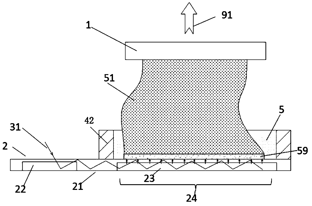
[0048] Such as figure 1 A light-curing 3D printing device shown includes a model board 1 and a light guide assembly 2 , and a curing model 51 is combined on the model board 1 . The light guide assembly 2 includes an optical waveguide 21 , an in-coupling portion 22 and an out-coupling portion 23 , and a region of the light guide assembly 2 corresponding to the out-coupling portion 23 is an out-coupling region 24 . The outcoupling area 24 of the light guide assembly 2 is set corresponding to the model plate 1, and the distance between the model plate 1 and the light guide assembly 2 can be controlled and adjusted, that is, the relative movement between the model plate 1 and the light guide assembly 2 can be carried out, such as The template plate 1 moves away from the light guide assembly 2 in the direction of the arrow 91 , or the light guide assembly 2 moves away from the template plate 1 . The relative movement between the model plate 1 and the light guide assembly 2 can als...

Embodiment 2

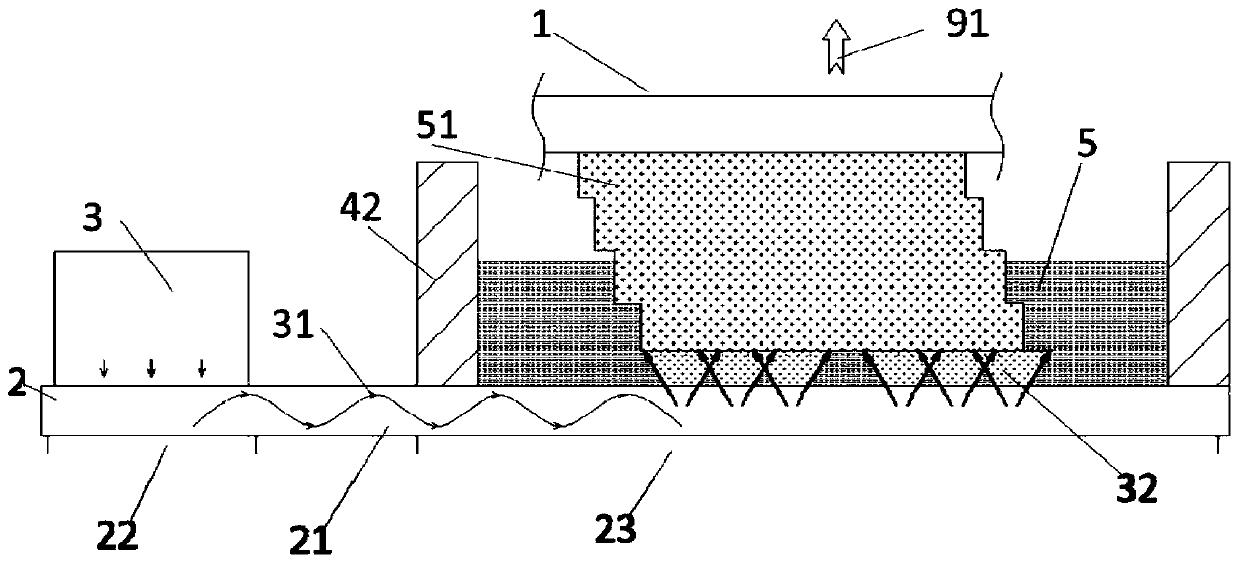
[0053] Such as figure 2 As shown, the light beam 31 emitted by the light source 3 shoots to the coupling part 22, and the coupling part 22 adjusts the direction of the light beam 31 and injects it into the optical waveguide 21. The figure shows that the light beam 31 propagates in the form of a sine wave in the optical waveguide 21 and reaches the outcoupling part 23. The outcoupling unit 23 adjusts the direction of the light beam 31 and emits it toward the light-transmitting plate 25 to irradiate the printing material 5 for photocuring. In the figure, the in-coupling part 22 and the out-coupling part 23 are externally placed on the outer surface of the optical waveguide 21, such as using gratings, of course, they can also be integrated inside the optical waveguide 21, such as mirrors or semi-transparent mirrors.

[0054] The difference between this embodiment and Embodiment 1 is that the outcoupling part 23 converts the light beam 31 in the outcoupling region 24 of the light...

Embodiment 3

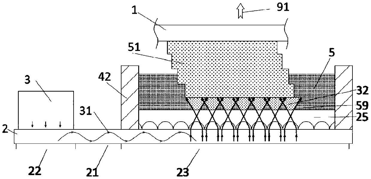
[0056] Such as image 3 As shown, the difference between this embodiment and Embodiment 1 is that a light-transmitting plate 25 is correspondingly provided between the outcoupling area 24 of the light guide assembly 2 and the model plate 1 . A microlens array 26 can also be provided inside the light-transmitting plate 25. After the light beam 31 emitted by the outcoupling unit 23 is transformed (such as focusing) by the micro-lens array 26 of the light-transmitting plate 25, it is directed from the light-transmitting plate 25 toward the model plate. The surface of 1 discretely emits, such as spaced, diffused emission, and forms several beam families 32 between the curing model 51 and the transparent plate 25, and at least part of adjacent beam families 32 may contact or partially overlap. The microlens array 26 can be a variable refractive index microlens array (as shown in the figure) embedded in the light-transmitting plate 25, or can be formed by a semi-convex lens array or...


PUM


Abstract

The invention relates to a photocuring 3D printing device. The device comprises a model plate, a curing model is combined on the model plate, and the photocuring 3D printing device also comprises a light guide assembly. The light guide assembly comprises a coupling-in part, an optical waveguide and a coupling-out part, the coupling-out part is arranged to correspond to the model plate, the coupling-in part converts an incident light beam, introduces the light beam into the optical waveguide, conducts the light beam to the coupling-out part and emits the light beam out of the coupling-out areabetween the light guide assembly and the model plate through conversion of the coupling-out part, and the model plate and the light guide assembly can move relatively. According to the present invention, the relative fixation of the position relation between a light source and a printing material container in the prior art is avoided, the flexible arrangement of the relative position relation between the light source and the printing material container can be achieved, the overall performance of the device is improved, and the printing efficiency and the printing precision can be improved.

Description

technical field [0001] The invention belongs to the technical field of 3D printing, in particular to a photocuring 3D printing device. Background technique [0002] 3D printing is a method of constructing objects by printing layer by layer based on digital model files, including SLA, DLP, LCD / LED and other light curing methods. For example, UV (ultraviolet light) or visible light is used to selectively cure the photocurable resin layer by layer to form a three-dimensional model. For example, the 3D printing method based on DLP (Digital Light Processing) is to project the surface imaging beam formed according to the section pattern of the three-dimensional model onto the photosensitive resin printing material to realize the curing of a single layer, so that the layers are cured and stacked to form a three-dimensional model; SLA (Stereo Lithography Apparatus) is to use the laser beam to focus on the photosensitive resin material through a mirror group (such as a lens or mirro...

Claims


Application Information

Patent Timeline
IPC IPC(8): B29C64/129B29C64/291B33Y30/00
CPCB29C64/129B29C64/291B33Y30/00
Inventor 季鹏凯
Owner YUANZHI TECH SHANGHAI CO LTD
Why Eureka
Try Eureka