
Continuous-conveying-type negative-pressure dust suction equipment for textile fabric

A textile fabric and negative pressure technology, which is applied in the field of continuous conveying textile fabric negative pressure dust collection equipment, can solve the problems of dust and fine velvet accumulation and overflow, inconvenient fabric movement and transportation, and low dust absorption efficiency, etc., to achieve fast Effective movement, improved dust absorption efficiency, and reduced production costs and energy consumption

Active Publication Date: 2019-12-03
孝感安华纺织有限公司
View PDF8 Cites 4 Cited by
  • Summary
  • Abstract
  • Description
  • Claims
  • Application Information

AI Technical Summary

Problems solved by technology

[0007] The purpose of the present invention is to provide a continuous conveying negative pressure dust collection equipment for textile fabrics to solve the above-mentioned background technology. It is proposed that the existing textile fabric dust collection equipment has low dust absorption efficiency. Residual and mixed dust and fine dust particles are easy to appear in the fabric. Long-term work will cause the accumulation and overflow of dust and fine velvet in the subsequent processing environment, which will affect the processing work. When dust is absorbed, the movement and movement of the fabric Inconvenient transportation, the use of additional electrical appliances for transportation, increased energy consumption during fabric vacuuming, increased production costs of equipment and economic expenditures for use

Method used


Image

  • Continuous-conveying-type negative-pressure dust suction equipment for textile fabric
  • Continuous-conveying-type negative-pressure dust suction equipment for textile fabric
  • Continuous-conveying-type negative-pressure dust suction equipment for textile fabric

Examples


Embodiment Construction

[0026] The following will clearly and completely describe the technical solutions in the embodiments of the present invention with reference to the accompanying drawings in the embodiments of the present invention. Obviously, the described embodiments are only some, not all, embodiments of the present invention. Based on the embodiments of the present invention, all other embodiments obtained by persons of ordinary skill in the art without making creative efforts belong to the protection scope of the present invention.

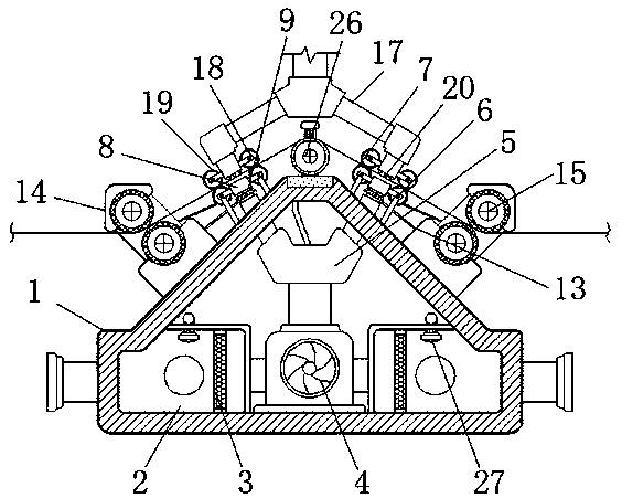
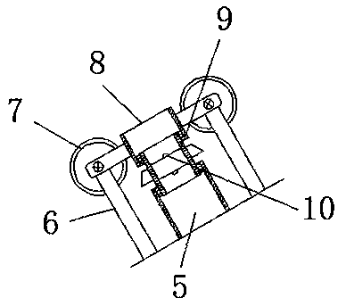
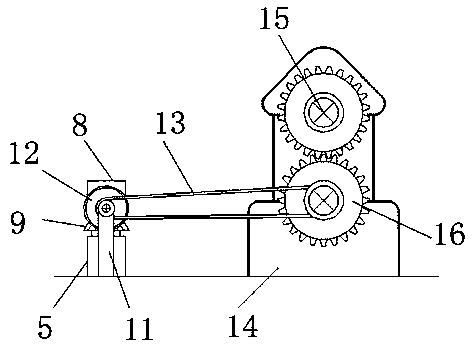
[0027] see Figure 1-6 , the present invention provides a technical solution: a continuous conveying negative pressure dust collection equipment for textile fabrics, including a housing 1, an air chamber 2, a dust filter 3, a fan 4, a shunt pipe 5, a first bracket 6, and a first runner 7. Air outlet pipe 8, connecting pipe 9, turbine 10, second bracket 11, bevel gear 12, crawler belt 13, positioning plate 14, guide roller 15, gear shaft 16, dust suction pipe 1...


PUM


Abstract

The invention discloses continuous-conveying-type negative-pressure dust suction equipment for textile fabric. The equipment comprises a housing, a fan, positioning plates, a dust suction pipe, a connecting piece and a negative-pressure dust suction device; the edge of the interior of the housing is provided with air cavities, a dust filtering net penetrates through the interior of each air cavity, air outlet pipes are connected with the end of a flow dividing pipe through connecting pipes, and a turbine is arranged in the middle of each connecting pipe; the positioning plates are fixed to theedge of the top of the housing, a guiding roller is rotatably installed on each positioning plate, the dust suction pipe is located over the housing and connected to an air inlet of the negative-pressure dust suction device, the connecting piece is installed at the center of the top of the housing, and the lower end of a connecting frame penetrates through the connecting piece and is connected tothe outer wall of a reciprocating screw rod. The continuous-conveying-type negative-pressure dust suction equipment for the textile fabric can effectively suck fine nap and dust in a fabric interlayer, the production cost and use energy consumption of the equipment are reduced, and the efficiency of dust suction work is improved.

Description

technical field [0001] The invention relates to the technical field of textile fabric processing, in particular to a continuously conveying negative pressure dust collection equipment for textile fabrics. Background technique [0002] In the processing of textile fabrics, fine velvet and dust particles left over from production and processing will remain on the fabrics. The residue of dust will cause obstacles to the subsequent processing of fabrics. At the same time, the accumulation of dust will cause production safety hazards in fabric processing areas, making fabrics Unnecessary additional economic losses occur in processing. Through the use of fabric vacuum equipment, the dust absorption on the outer surface of the fabric is prepared and effectively, reducing the overflow during the dust absorption process of the fabric, maintaining the environmental sanitation of the production and processing area, and protecting the processing area at the same time personal and proper...

Claims


Application Information

Patent Timeline
Patent Type & Authority Applications(China)
IPC IPC(8): D06G1/00
CPCD06G1/00
Inventor 李蕾
Owner 孝感安华纺织有限公司
Learn More