
Thrust vector control system and method based on plasma synthetic jet exciter

A thrust vector control and plasma technology, which is applied in aircraft control, flight direction control, transportation and packaging, etc., can solve the problems of increasing the complexity of the device and unfavorable maintenance, and achieve the effects of simple structure, stable operation and fast response frequency.

Inactive Publication Date: 2019-12-03
NANJING UNIV OF SCI & TECH
View PDF6 Cites 3 Cited by
  • Summary
  • Abstract
  • Description
  • Claims
  • Application Information

AI Technical Summary

Problems solved by technology

Except for the synthetic jet nozzle, the above-mentioned fluid vector nozzles all need an external air source input, which greatly increases the complexity of the device, puts a test on the reliability of the device, and is not conducive to maintenance

Method used


Image

  • Thrust vector control system and method based on plasma synthetic jet exciter
  • Thrust vector control system and method based on plasma synthetic jet exciter
  • Thrust vector control system and method based on plasma synthetic jet exciter

Examples


Embodiment Construction

[0023] The specific implementation manners of the present invention will be further described below in conjunction with the accompanying drawings.

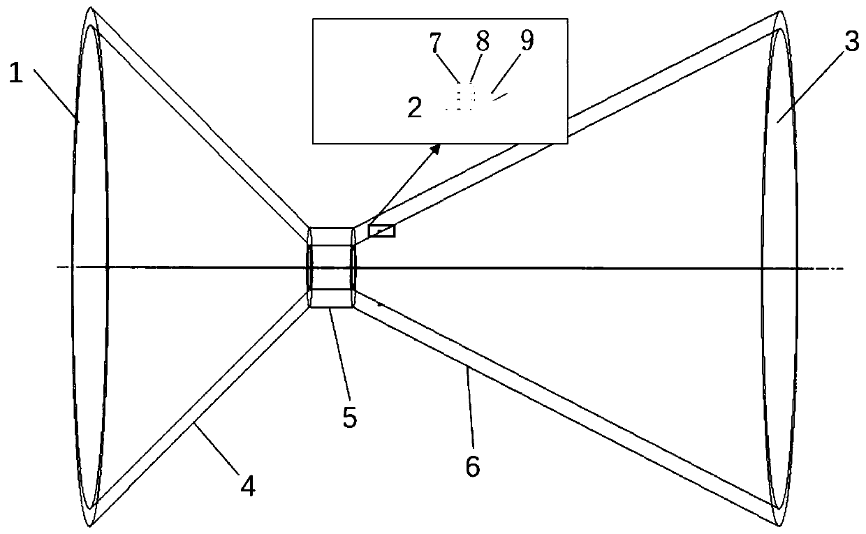
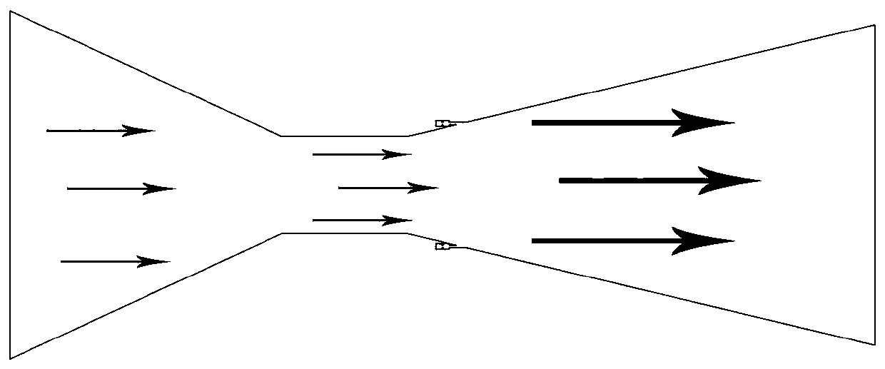
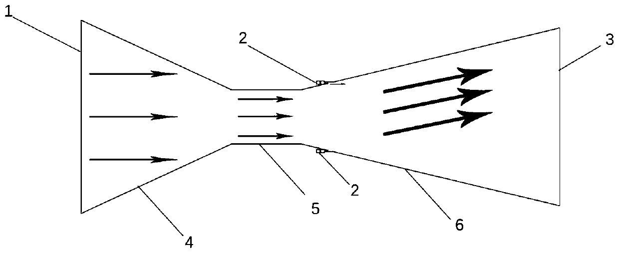
[0024] A thrust vector control system based on a plasma synthetic jet actuator, comprising a nozzle 1 and a plurality of two-electrode plasma jet actuators 2 arranged between the inner and outer walls of the expansion section 6 of the nozzle 1, the two-electrode plasma Jet exciter 2 comprises two electrodes 7, exciter cavity 8, power supply and throat nozzle 9, and described two electrodes 7 are arranged in exciter cavity 8, and described power supply is connected with two electrodes 7, so The outlet of the exciter cavity 8 communicates with the inner wall of the expansion section 6 through the throat nozzle 9 .

[0025] Further, the nozzle 1 is a Laval nozzle, including a constriction section 4 , a throat transition section 5 and an expansion section 6 , and a plurality of two-electrode plasma jet actuators 2 are arranged symmetr...


PUM


Abstract

The invention discloses a thrust vector control system and method based on a plasma synthetic jet exciter. The system comprises a spray pipe and a plurality of two-electrode plasma jet exciters arranged between the inner wall and the outer wall of an expansion section of the spray pipe; each two-electrode plasma jet exciter comprises two electrodes, an exciter cavity, a power supply and a throat spray pipe, wherein the two electrodes are arranged in the exciter cavity, the power supply is connected with the two electrodes, and an outlet of the exciter cavity is communicated with the inner wallsurface of the expansion section through the throat spray pipe. When main jet flows through the expansion sections of the spray pipes, high voltage is applied to two electrodes of each two-electrodeplasma jet exciter, discharge is generated in each exciter cavity to break down air to form high-temperature and high-pressure plasma, and therefore high-speed gas jet is generated at an outlet. Underthe interaction of high-speed gas jet flow and main jet flow in the expansion sections of the spray pipes, the main jet flow deflects towards the expected direction, and therefore the purpose of thrust vector control is achieved. The system is simple in structure, high in response frequency and high in jet speed.

Description

technical field [0001] The invention relates to the field of aircraft engine thrust vector control, in particular to a thrust vector control system and method based on a plasma synthetic jet actuator. Background technique [0002] Thrust vector control technology refers to a method of controlling the flight of an aircraft by changing the direction of the engine jet airflow. For the aircraft that does not adopt the thrust vector control technology, the ejected airflow of the engine is parallel to the axis of the nozzle, so the thrust generated is parallel to the axis of the nozzle, which is used to overcome the flight resistance and provide the power for the aircraft to accelerate. Thrust vectoring technology generates direct control force from the thrust component of the engine, which can directly control the attitude of the aircraft, greatly improving the maneuverability of the aircraft. Traditional thrust vectoring technology is mainly mechanical passive flow control, suc...

Claims


Application Information

Patent Timeline
IPC IPC(8): F02K1/28F02K1/78B64C15/02
CPCB64C15/02F02K1/28F02K1/78
Inventor 张小兵李晋峰
Owner NANJING UNIV OF SCI & TECH
Learn More