A gear deburring process

A technology for deburring and gears, which is applied in the field of gears, can solve the problems of strong corrosion on the surface of castings, takes tens of seconds, and poor deburring effect, and achieves the effects of short deburring time, fast spraying speed and avoiding damage

Active Publication Date: 2020-01-10
NANTONG ZHONGLV GEAR CO LTD
View PDF1 Cites 1 Cited by
  • Summary
  • Abstract
  • Description
  • Claims
  • Application Information

AI Technical Summary

Problems solved by technology

[0002] Gears refer to the mechanical elements with gears on the wheel rim that continuously mesh to transmit motion and power. Wheels appeared very early in transmission applications. Because of their smooth and continuous transmission, they are widely used in various fields of machinery. Gears are used in gearboxes. One of the essential components, the quality of the gear determines the stability of the transmission, the accuracy of the reduction ratio, and the vibration and noise transmitted. In the cycloid reducer, the gear tooth profile accuracy and flatness requirements Higher, due to the special shape of the gear, ordinary grinding equipment may damage the tooth profile during the deburring process, making it difficult for the tooth profile to be mechanized in the deburring work
[0003] Patent No. 201010208784.9 An electrochemical deburring equipment and its deburring process proposes the use of electrochemical methods to achieve the effect of deburring. Under the action of the electrolyte and the electrolyte, the two poles exchange charges, and the deburring of the casting is achieved through discharge, but the current is large, and the outflow of the electrolyte is small, there is a risk of the casting being broken down, and the gear structure is small. If there is no The limit is easy to shift, which affects the deburring effect. Due to the less electrolyte outflow, the deburring effect is poor. It takes tens of seconds to deal with a burr, and requires a high concentration of electrolyte, which is highly irritating and harmful to castings. The surface is highly corrosive and harmful to the human body. At the same time, due to the small amount of electrolyte outflow, the burrs are still attached to the gear surface. The gear surface needs to be cleaned with water and cleaning solution. The cleaning process is cumbersome, so this deburring process is not applicable. Due to the gear structure, and the deburring effect is poor, it takes a long time

Method used


Image

  • A gear deburring process
  • A gear deburring process
  • A gear deburring process

Examples


Embodiment 1

[0046] Present embodiment is a kind of gear deburring process, and its specific steps are as follows:

[0047] (1), construction of deburring device: deburring device includes

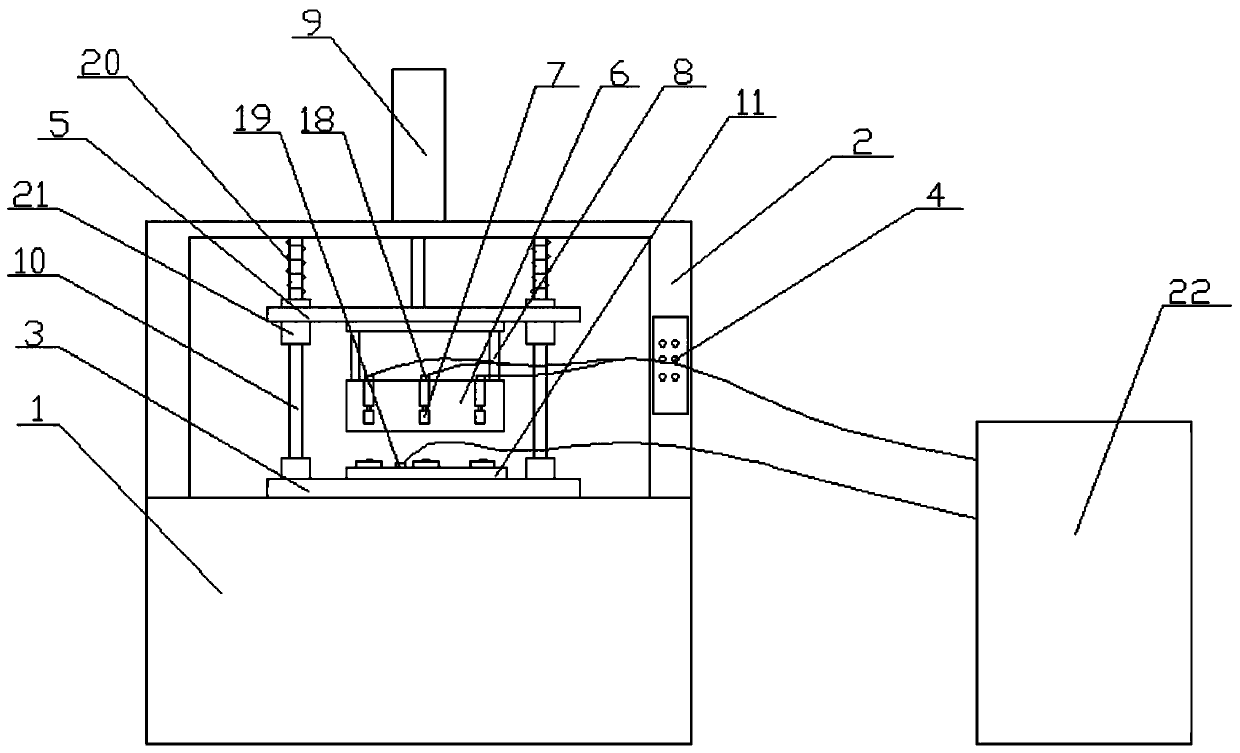
[0048] A body group, the body group includes an electrolyte tank 1, and a casing 2 placed around the top of the electrolyte tank 1. The front part of the casing 2 is an open structure, and a working area is formed inside it. Boss 3, there is a gap between the boss 3 and the electrolyte tank 1 to allow the electrolyte to flow in, and the housing 2 is provided with a control box 4;

[0049] An upper module, the upper module includes a connecting block 5 and a pressure cover 6, the lower end surface of the pressure cover 6 is an open structure, and the inside of the pressure cover 6 is a cavity structure, and the inside of the pressure cover 6 is provided with a plurality of horizontal and evenly arranged The set briquetting block 7 is provided with a plurality of vertically arranged connecting rods 8 be...

Embodiment 2

[0059] Present embodiment is a kind of gear deburring process, and its specific steps are as follows:

[0060] (1), construction of deburring device: deburring device includes

[0061] A body group, the body group includes an electrolyte tank 1, and a casing 2 placed around the top of the electrolyte tank 1. The front part of the casing 2 is an open structure, and a working area is formed inside it. Boss 3, there is a gap between the boss 3 and the electrolyte tank 1 to allow the electrolyte to flow in, and the housing 2 is provided with a control box 4;

[0062] An upper module, the upper module includes a connecting block 5 and a pressure cover 6, the lower end surface of the pressure cover 6 is an open structure, and the inside of the pressure cover 6 is a cavity structure, and the inside of the pressure cover 6 is provided with a plurality of horizontal and evenly arranged The set briquetting block 7 is provided with a plurality of vertically arranged connecting rods 8 be...

Embodiment 3

[0072] Present embodiment is a kind of gear deburring process, and its specific steps are as follows:

[0073] (1), construction of deburring device: deburring device includes

[0074] A body group, the body group includes an electrolyte tank 1, and a casing 2 placed around the top of the electrolyte tank 1. The front part of the casing 2 is an open structure, and a working area is formed inside it. Boss 3, there is a gap between the boss 3 and the electrolyte tank 1 to allow the electrolyte to flow in, and the housing 2 is provided with a control box 4;

[0075] An upper module, the upper module includes a connecting block 5 and a pressure cover 6, the lower end surface of the pressure cover 6 is an open structure, and the inside of the pressure cover 6 is a cavity structure, and the inside of the pressure cover 6 is provided with a plurality of horizontal and evenly arranged The set briquetting block 7 is provided with a plurality of vertically arranged connecting rods 8 be...


PUM


Abstract

The invention relates to a gear burr removing technology. The technology comprises the following specific steps that 1, a burr removing device is constructed; 2, a gear is placed; 3, conducting and discharging are carried out; 4, an electrolyte is sprayed; 5, the gear is washed ultrasonically; 6, antirust treatment is carried out; and 7, the gear is naturally dried in air and delivered from storage. The technology has the following advantages that an anode terminal and a cathode terminal are utilized for conducting and discharging, the electrolyte is sprayed to the gear fast from bottom to top, the spraying speed is high, the electrolyte is sprayed in a centralized manner, and the burr removing effect is achieved; meanwhile, the burr removing effect is remarkable, the risk that the gear isbroken down is avoided, time for burr removing is short, and efficiency is high; the concentration of sodium nitrate is low, harm to the human body is avoided, corrosion to the surface of the gear isavoided, and meanwhile, the good burr removing effect can be ensured; and as the electrolyte spraying speed is high and the flow amount is large, the complex washing step in the later period is omitted, the gear only needs to be washed with clear water, the gear is washed ultrasonically, and thus greasy dirt on the surface of the gear can be decomposed and emulsified.

Description

Technical field: [0001] The invention relates to the field of gears, in particular to a gear deburring process. Background technique: [0002] Gears refer to the mechanical elements with gears on the wheel rim that continuously mesh to transmit motion and power. Wheels appeared very early in transmission applications. Because of their smooth and continuous transmission, they are widely used in various fields of machinery. Gears are used in gearboxes. One of the essential components, the quality of the gear determines the stability of the transmission, the accuracy of the reduction ratio, and the vibration and noise transmitted. In the cycloid reducer, the gear tooth profile accuracy and flatness requirements Due to the special shape of the gear, ordinary grinding equipment may damage the tooth profile during the deburring process, making it difficult to mechanize the tooth profile in the deburring work. [0003] Patent No. 201010208784.9 An electrochemical deburring equipme...

Claims


Application Information

Patent Timeline
Patent Type & Authority Patents(China)
IPC IPC(8): B23H3/00B23H9/02
CPCB23H3/00B23H9/02
Inventor 潘志进
Owner NANTONG ZHONGLV GEAR CO LTD
Why Eureka
Try Eureka