Carbondeposition prevention oil sprayer
A fuel injector and carbon deposition prevention technology, which is applied in fuel injection control, machines/engines, fuel injection devices, etc., can solve problems such as high fuel injection pressure and inability to completely remove carbon deposits, so as to reduce incomplete combustion, The effect of reducing the amount of sediment formation and strong flushing action
- Summary
- Abstract
- Description
- Claims
- Application Information
AI Technical Summary
Problems solved by technology
Method used
Image
Examples
Embodiment 1
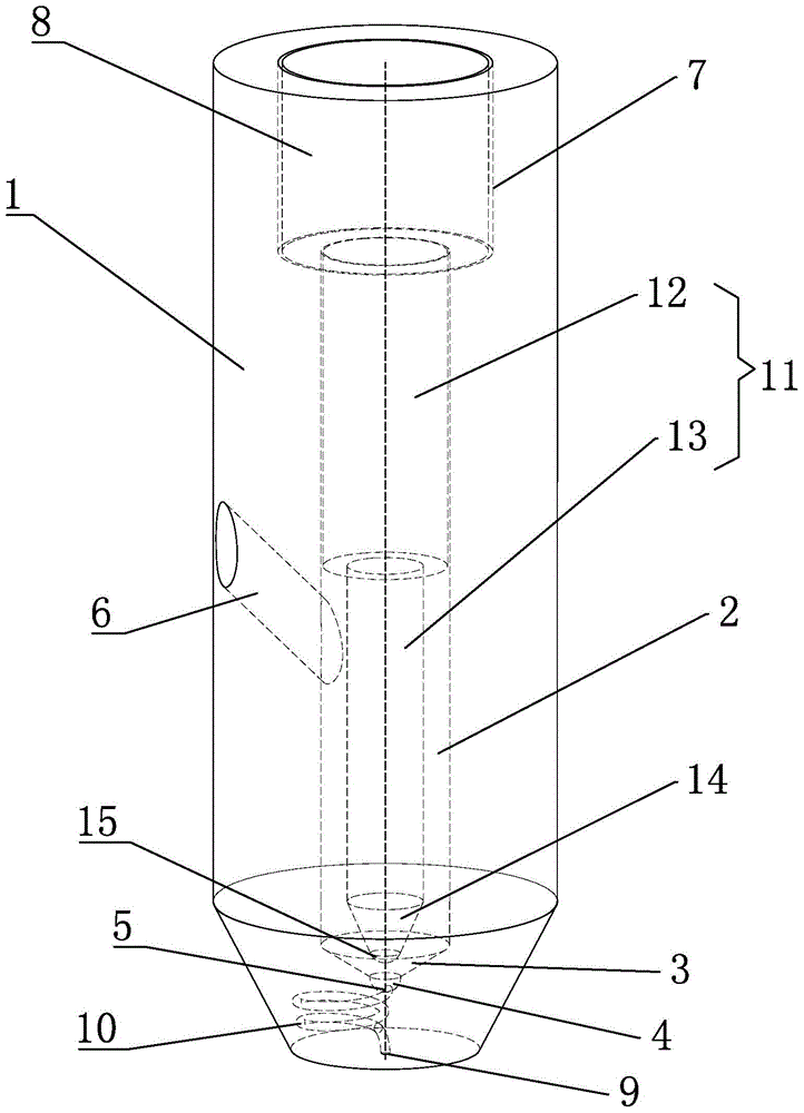
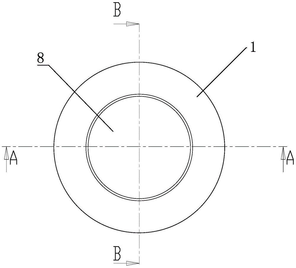
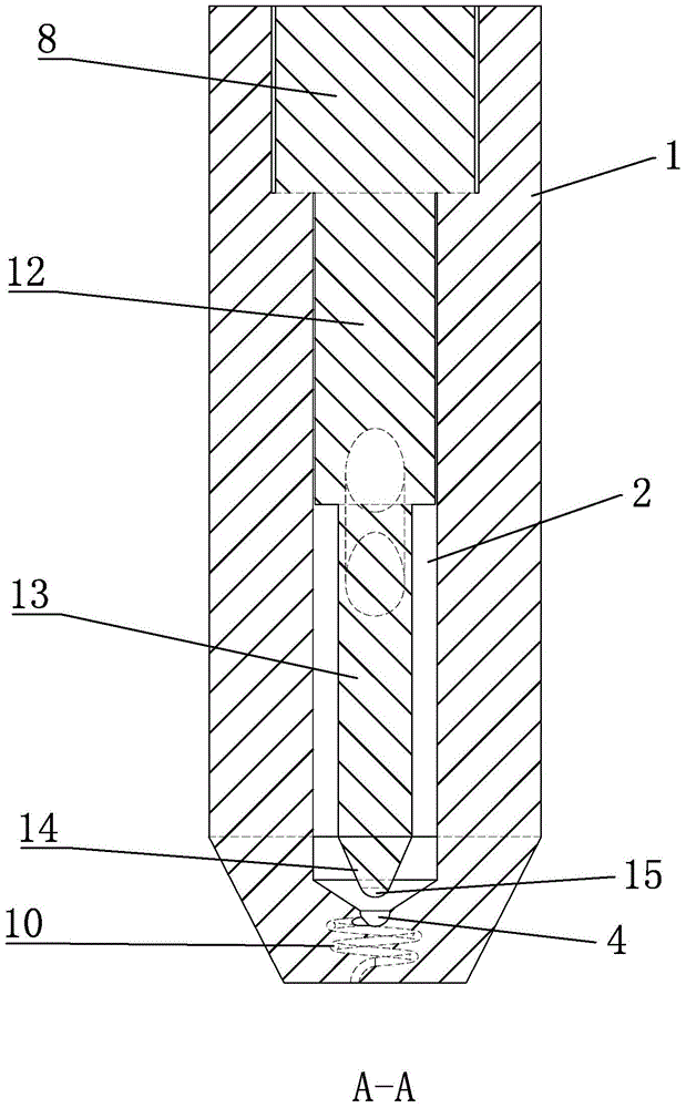
[0042] Such as Figure 1-7 As shown, the anti-carbon deposit injector of the present invention includes: a valve body 1, a plunger chamber 2, a tapered chamber 3, a valve seat 4, a liquid outlet 5, a liquid inlet hole 6, a control groove 7, and a controller 8. Liquid injection port 9, drainage channel 10, plunger 11, upper plunger 12, lower plunger 13, cone 14, valve needle 15, lower edge 16.
[0043] The top of the cylindrical valve body 1 is provided with a cylindrical control groove 7, and the lower end of the control groove 7 is provided with a cylindrical plunger chamber 2, the plunger chamber 2 communicates with the control groove 7, and the bottom end of the plunger chamber 2 There is a tapered chamber 3 with the tip pointing down, and the bottom end of the tapered chamber 3 is provided with a valve seat 4 with a hemispherical inner wall. The control groove 7, the plunger chamber 2, the tapered chamber 3, and the valve seat 4 are respectively Set in the valve body 1 an...
Embodiment 2
[0057] Such as Figure 7 As shown, the anti-carbon deposit injector of this embodiment differs from that of Embodiment 1 in that: Figure 8-9 As shown, the liquid inlet hole 6 is located in the middle and upper part of the valve body 1. When the plunger 11 moves to the uppermost position, the liquid inlet hole 6 is connected with the outer surface of the lower plunger 13 and the cylindrical cavity between the plunger cavity 2 so that gasoline is injected into the injector; when the plunger 11 moves to the lowest position, the upper plunger 12 closes the inner end of the liquid inlet hole 6, and the lower end edge 16 of the upper plunger 12 is lower than the liquid inlet hole 6 The lower edge of the inner end is low and the distance G between the two is 0.05-0.25mm (preferably 0.1, 0.15 or 0.2 or 0.24mm).
[0058] The working method of the anti-carbon deposit injector in this embodiment includes:
[0059] (1) The controller 8 keeps the plunger 11 at the lowest position, the o...
Embodiment 3
[0067] A gasoline engine comprising the anti-carbon deposit injector described in Embodiment 1 or 2 above.
PUM
 Abstract
Description
Claims
Application Information
 - R&D
- Intellectual Property
- Life Sciences
- Materials
- Tech Scout
- Unparalleled Data Quality
- Higher Quality Content
- 60% Fewer Hallucinations
Browse by: Latest US Patents, China's latest patents, Technical Efficacy Thesaurus, Application Domain, Technology Topic, Popular Technical Reports.
© 2025 PatSnap. All rights reserved.Legal|Privacy policy|Modern Slavery Act Transparency Statement|Sitemap|About US| Contact US: help@patsnap.com


