Friction plate structure and manufacturing method thereof

A manufacturing method and technology of friction linings, which are applied to friction linings, chemical instruments and methods, gear transmission mechanisms, etc., can solve the problems of frictional performance limitation, inability to carry, high frictional consumption, etc., to achieve excellent self-lubrication and reduce risks. , Excellent wear resistance and durability

Inactive Publication Date: 2019-12-03
LINKWIN TECH
View PDF6 Cites 2 Cited by
  • Summary
  • Abstract
  • Description
  • Claims
  • Application Information

AI Technical Summary

Problems solved by technology

[0005] The friction plate made of metal has the problem of metal corrosion, and it is also easy to produce harsh and sharp noises due to excessive wear or unevenness of the surface of the friction plate during use
[0006] The paper-based friction plate has the advantage of relatively low material cost, but its friction performance is relatively limited, and its durability is not good. Its structure cannot bear excessive friction consumption, so it can only be used in mechanical friction with low demand. In the field of machinery, it is not enough for high-end machinery with high friction performance requirements

Method used


Image

  • Friction plate structure and manufacturing method thereof
  • Friction plate structure and manufacturing method thereof
  • Friction plate structure and manufacturing method thereof

Examples


Embodiment Construction

[0028] In order to make the purpose, technical solutions and advantages of the embodiments of the present invention clearer, the technical solutions in the embodiments of the present invention will be clearly and completely described below in conjunction with the drawings in the embodiments of the present invention. Obviously, the described embodiments It is a part of embodiments of the present invention, but not all embodiments. Based on the embodiments of the present invention, all other embodiments obtained by persons of ordinary skill in the art without making creative efforts belong to the protection scope of the present invention.

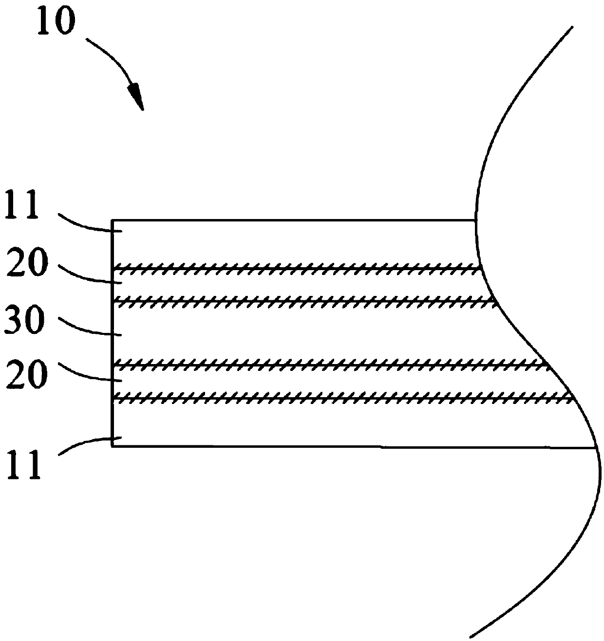
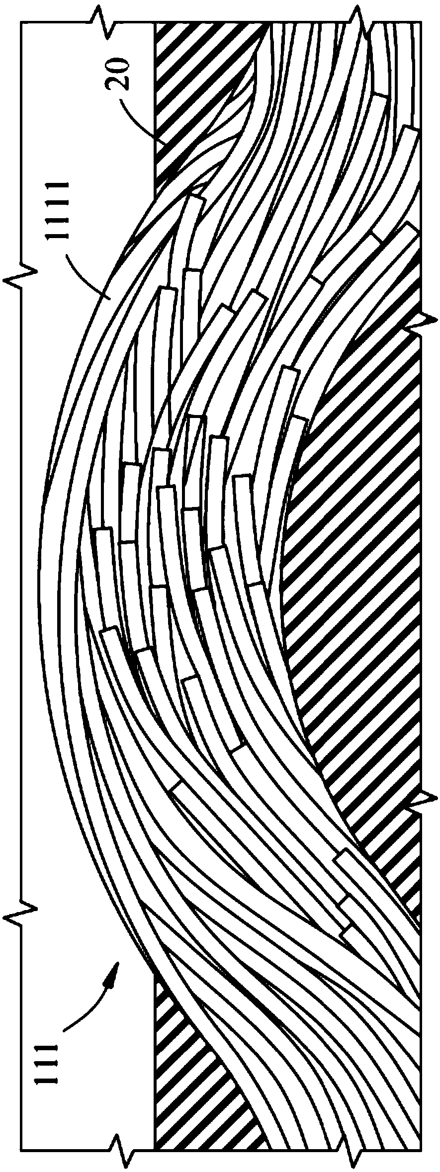
[0029] Such as Figure 1 ~ Figure 3 As shown, in the friction plate structure 10 of the present invention, two pieces of carbon fiber cloth 11 are stacked in the order of carbon fiber cloth 11, adhesive material 20, support material 30, adhesive material 20 and carbon fiber cloth 11 so that the thickness is between 0.45 mm and 1 mm. The fric...


PUM

PropertyMeasurementUnit
thicknessaaaaaaaaaa
tensile strengthaaaaaaaaaa

Abstract

The invention provides a friction plate structure and a manufacturing method thereof. The thickness of the friction plate structure ranges from 0.45 mm to 1 mm, and the friction plate structure is formed by laminating a carbon fiber sheet, an adhesive material, a support material, an adhesive material, and another carbon fiber sheet orderly, wherein the carbon fiber cloth is formed by weaving a plurality of fiber bundles in a staggered manner, each fiber bundle is formed by twisting a plurality of short fibers and locally overlapping and interwinding the plurality of short fibers in the axialdirection of the fiber bundle, and the length direction of each short fiber corresponds to the axial direction of the fiber bundles; the bonding material permeates into the fiber bundles of the carbonfiber cloth until the impregnation rate is greater than 80%, and the fiber bundles of the carbon fiber cloth are partially exposed out of the bonding material in a peak area of a wave crest. The radial tensile strength of the friction plate structure ranges from 90 MPa to 177 MPa, the axial tensile strength of the friction plate structure ranges from 60 MPa to 136 MPa, and the dynamic and staticfriction ratio of the friction plate structure ranges from 0.8 to 0.98.

Description

technical field [0001] The invention relates to a friction plate structure, in particular to a friction plate structure containing discontinuous carbon fiber and highly impregnated and self-lubricated by resin and a manufacturing method thereof. Background technique [0002] Friction material is a necessity applied to power machinery. Its principle of action is mainly to rely on the friction relationship between the friction material and the dual mechanical device to produce the effect of power transmission or braking. Most mechanical appliances or equipment are equipped with friction materials, so the quality of the friction materials directly affects the performance of the mechanical appliances or equipment, and even relates to the life safety of operators. [0003] At present, the friction plate materials used in power machinery mainly include asbestos, metal or paper-based materials, all of which have their defects or limitations, such as: [0004] The earliest develope...

Claims


Application Information

Patent Timeline
Patent Type & Authority Applications(China)
IPC IPC(8): F16D69/02B32B9/00B32B9/04B32B5/02B32B17/02B32B37/06B32B37/10B32B37/12
CPCB32B5/02B32B5/08B32B5/26B32B37/06B32B37/10B32B37/12B32B2262/10B32B2262/101B32B2262/106B32B2262/14F16D69/023F16D2069/008F16D2200/0052F16D2200/0073F16D2200/0078F16D2200/0082
Inventor 郑益庆江以文吴昌谋林柏均
Owner LINKWIN TECH
Why Eureka
Try Eureka