Heat exchanger applied to gas water heater

A gas-fired water heater and heat exchanger technology, applied in heat exchange equipment, water heaters, fluid heaters, etc., can solve the problems of rising shell surface temperature, occupying space, and high heat loss, so as to improve the heat exchange rate, The effect of reducing the occupied space and reducing the surface temperature rise

Pending Publication Date: 2019-12-03
NINGBO FOTILE KITCHEN WARE CO LTD
View PDF0 Cites 0 Cited by
  • Summary
  • Abstract
  • Description
  • Claims
  • Application Information

AI Technical Summary

Problems solved by technology

Such a design has the following disadvantages: first, there is a gap between the shell and the coiled tube, and the heat exchange performance is not high; second, the temperature rise of the shell surface is high, and ther

Method used


Image

  • Heat exchanger applied to gas water heater
  • Heat exchanger applied to gas water heater
  • Heat exchanger applied to gas water heater

Examples


Example Embodiment

[0015] The present invention will be further described in detail below in conjunction with the embodiments of the drawings.

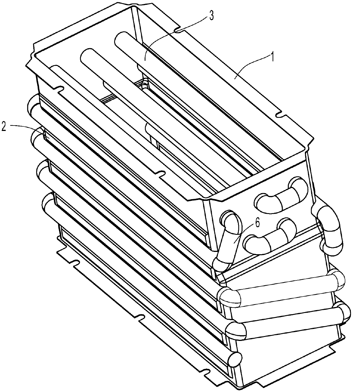
[0016] Such as image 3 , Figure 4 with Figure 5 As shown, the heat exchanger in this embodiment is applied to a gas water heater, and specifically includes a shell 1, a coil tube arranged on the outer wall of the shell 1, and an inner tube arranged in the shell. The outer wall of the shell 1 has a strip shape The first groove 11, the outer wall of the housing 1 is provided with a bonding plate 2 that is closely attached to it, and a strip-shaped second groove 21 is formed on the bonding plate 2, and the second groove 21 is butted with the first groove 11 Join together to form a water pipe channel 4.

[0017] The first grooves 11 are multiple and arranged up and down at intervals. Correspondingly, the second grooves 21 are also multiple and arranged up and down at intervals. A strip-shaped third groove 22 is formed between the first grooves 11, and corre...


PUM


Abstract

The invention discloses a heat exchanger applied to a gas water heater. The heat exchanger comprises a shell (1) and a coil pipe arranged on the outer wall of the shell (1), and is characterized in that a strip-shaped first groove (11) is formed on the outer wall of the shell (1), an attaching plate (2) is attached to the outer wall of the shell (1), a strip-shaped second groove (21) is formed onthe attaching plate (2), and the second groove (21) and the first groove (11) are in butt joint and are spliced to form a water pipe channel (4). The shell and the water pipe channel are combined intoa whole and are in seamless connection, so that the heat exchange with the external air can be reduced, the heat loss is reduced, the heat exchange rate is increased, and the occupied space is reduced. And more heat is transferred into the water through the pipe wall and the shell, so that the surface temperature rise is reduced.

Description

Technical field [0001] The invention relates to a heat exchanger (also known as a heat exchanger), in particular to a heat exchange device applied to a gas water heater. Background technique [0002] In the field of gas water heaters, the shell 1a and the coiled tube 2a in the heat exchanger are mostly two separate parts, such as figure 1 with figure 2 As shown, the coiled tube 2a is attached to the outer wall of the housing 1a for heat exchange, thereby increasing the water temperature. This design has the following shortcomings: firstly, there is a gap between the shell and the coiled tube, and the heat exchange performance is not high; secondly, the temperature rise of the shell surface is high, and there is a safety hazard; thirdly, the shell surface is in direct contact with the air, and the heat loss is relatively high. High; Finally, the coiled tube is attached to the outer wall of the shell, occupying space. Summary of the invention [0003] The technical problem to be s...

Claims


Application Information

Patent Timeline
IPC IPC(8): F24H1/16F24H9/00F28F1/00F28F1/02F28F9/00F28F9/26
CPCF24H1/165F24H9/0005F28F1/00F28F1/022F28F9/001F28F9/26
Inventor 魏苗苗朱海龙沈文权王世平周高云
Owner NINGBO FOTILE KITCHEN WARE CO LTD
Why Eureka
Try Eureka