Equipment and process for liquefaction of LNG boiloff gas

Active Publication Date: 2007-11-08
AIR WATER GAS SOLUTIONS INC
View PDF6 Cites 15 Cited by
  • Summary
  • Abstract
  • Description
  • Claims
  • Application Information

AI Technical Summary

Benefits of technology

[0018]2. A small refrigerant stream is liquefied, reduced in pressure, and introduced into the cold end of the main heat exchanger in order to achieve fin

Problems solved by technology

Such systems are machinery-intensive, i.e. the machinery size, weight, cost, and potential maintenance constitute major factors in the practicality and economy of the installation.
Compression of cold gas has a thermodynamic penalty and leads to higher energy consumption.2. A small refr

Method used


Image

  • Equipment and process for liquefaction of LNG boiloff gas
  • Equipment and process for liquefaction of LNG boiloff gas
  • Equipment and process for liquefaction of LNG boiloff gas

Examples


example

[0036]kgmoles / hr=kilogram moles per hour (flow)

[0037]° C.=degrees Celsius (temperature)

[0038]bar=bar (absolute pressure)

[0039]composition %=molar percentages

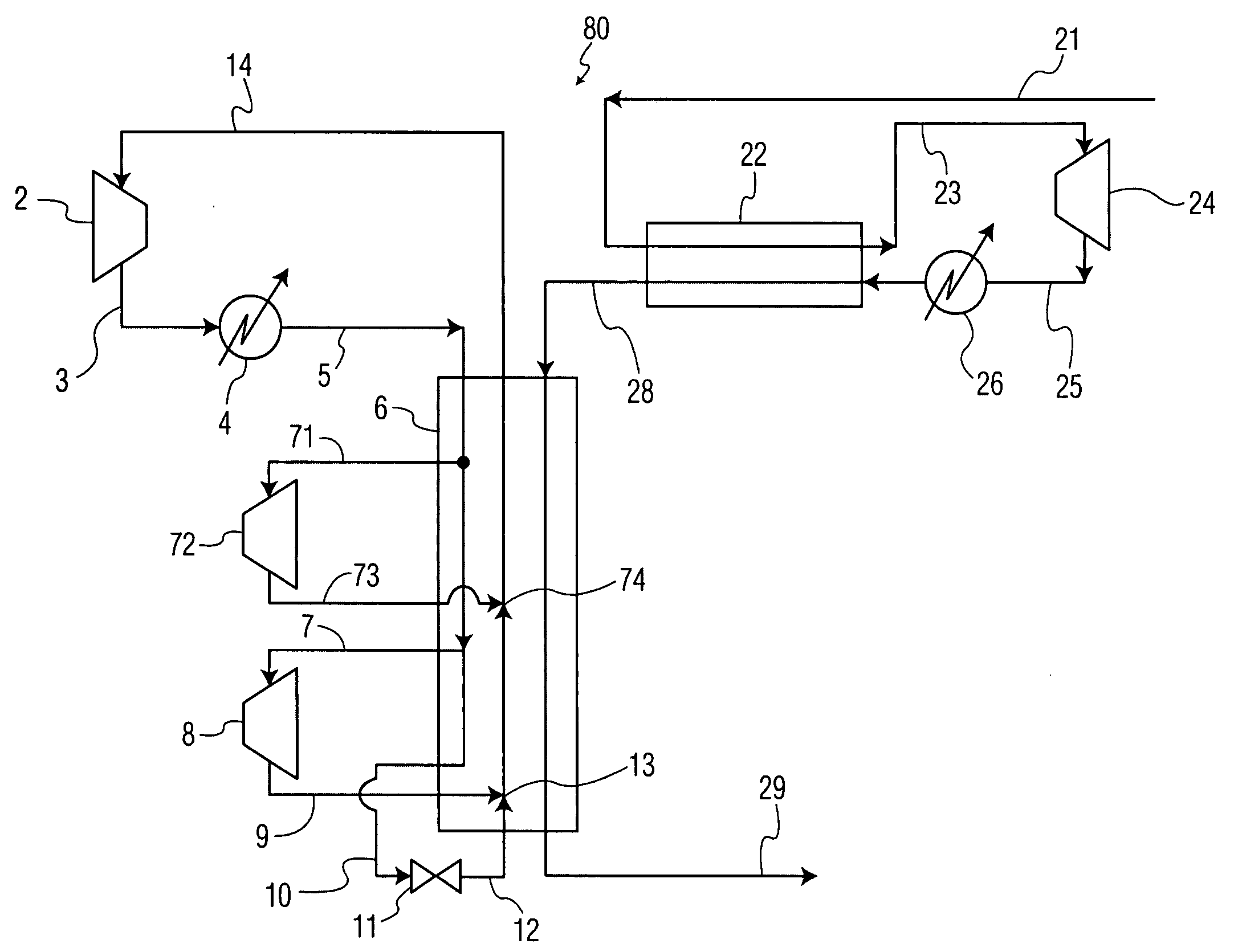
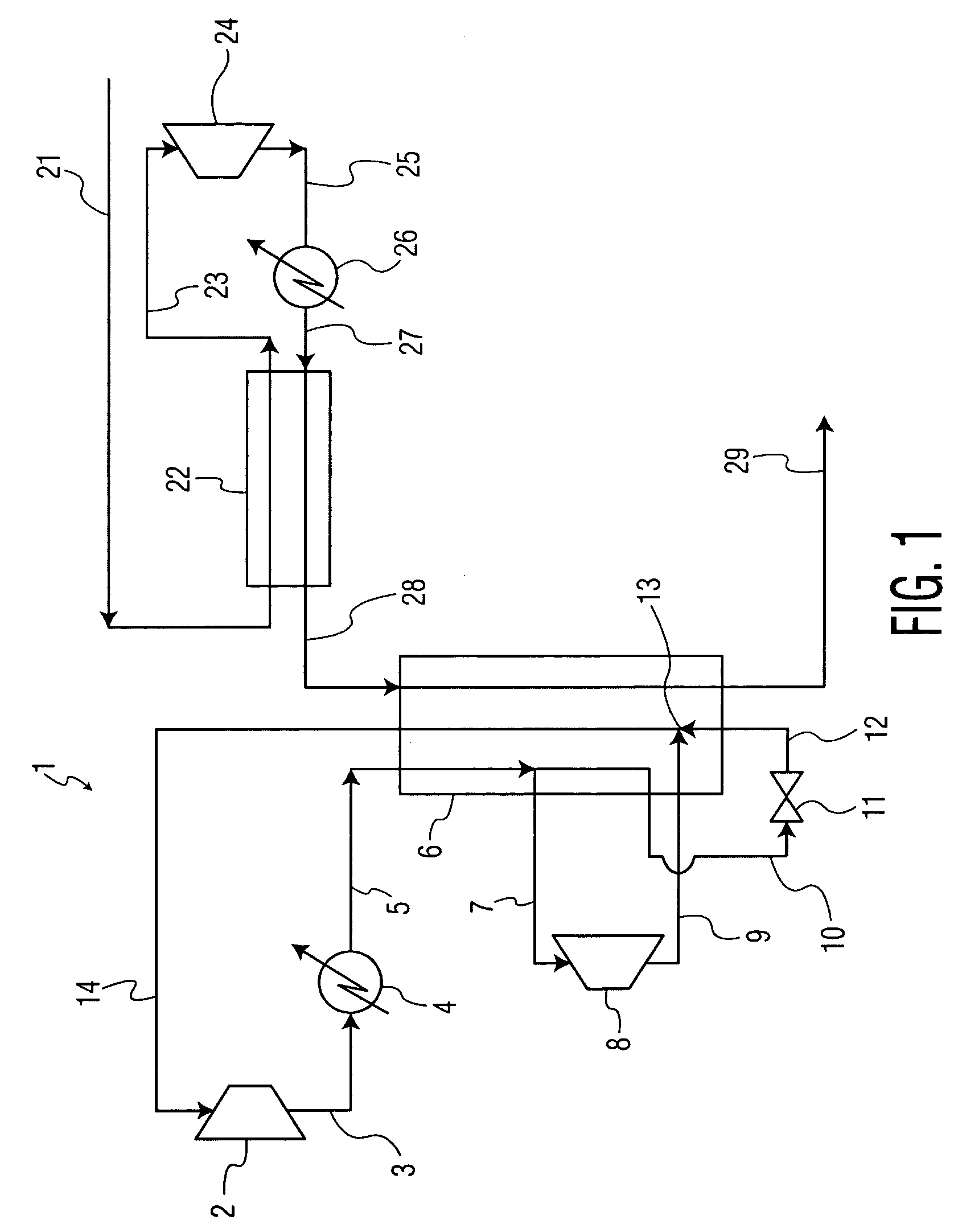
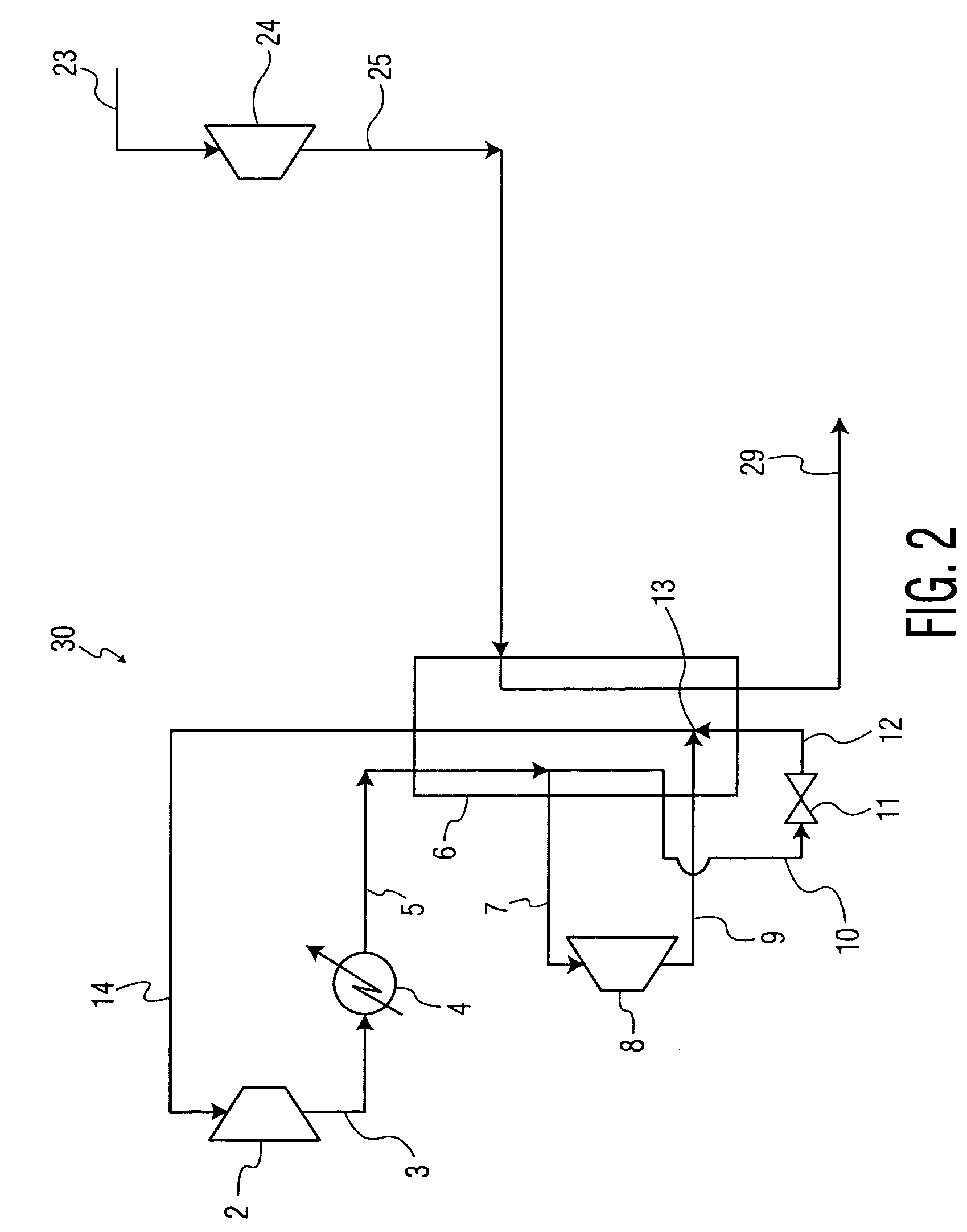
[0040]FIG. 5 shows a process for the reliquefaction of boiloff gas 21 evolved from the cargo tanks of an ocean-going LNG transport vessel, where the boiloff gas evolution rate is 395.9 kgmoles / hr, reaching the deck at a temperature of −130° C. and a pressure of 1.060 bar. The boiloff gas composition is 91.46% methane; 8.53% nitrogen; and 0.01% ethane. The boiloff gas is warmed in heat exchanger 22 and stream 23 exits at 41° C. and 1.03 bar. Stream 23 enters boiloff gas compressor 24 and is compressed to 2.3 bar and 122° C. Stream 25 is cooled in aftercooler 26 to 43° C. and 2.2 bar. Typically, cooling water is the cooling medium in indirect heat transfer with the boiloff gas for this aftercooler and other aftercoolers in the process. The cooled, compressed gas 27 enters heat exchanger 22 in indirect heat transfer with stream 21,...


PUM


Abstract

A design for equipment and process for reliquefaction of LNG boiloff gas, primarily for shipboard installation, has high thermodynamic efficiency and lower capital cost, smaller size (volume, footprint), lower weight, and less need for maintenance than systems utilizing the prior art. The main refrigerant gas compressor is reduced to a single stage turbocompressor. Optional elements include: compression of boiloff gas at ambient temperature; compression of boiloff gas in one or two stages; turboexpansion of refrigerant gas incorporating one or two turboexpanders; turboexpander energy recovery by mechanical loading, compressor drive, or electric generator; refrigerant sidestream for cooling at the lowest temperatures.

Description

CROSS-REFERENCE TO RELATED APPLICATION[0001]This application is entitled to the benefit of Provisional Patent Application Ser. No. 60 / 798,696 filed May 23, 2006.FIELD OF THE INVENTION[0002]The present invention is directed to the reliquefaction of boiloff vapors from liquefied natural gas (LNG) storage tanks. Such storage tanks are used on large ocean-going vessels for transport of LNG, and are in widespread use on land in many applications.BACKGROUND ART[0003]This invention is particularly applicable to shipboard re-liquefaction of boil-off natural gas from LNG carriers, where simplicity, weight, energy consumption, cost, and maintenance must strike an economic balance.[0004]Such systems have typically incorporated a refrigeration cycle, composed of a working fluid such as nitrogen gas in multi-stage compression and one or two turboexpanders which may drive compressors; and the boiloff gas is typically compressed in two stages. Such prior art is shown in existing patents: WO 98 / 430...

Claims


Application Information

Patent Timeline
IPC IPC(8): F25J1/00
CPCF25J1/0025F25J1/004F25J1/005F25J1/0052F25J1/0072F25J2270/16F25J1/0277F25J1/0288F25J2230/08F25J2230/30F25J1/0204F25J1/0221
Inventor MOSTELLO, ROBERT ANTHONY
Owner AIR WATER GAS SOLUTIONS INC
Why Eureka
Try Eureka