Method for improving temperature gradient in high-temperature tension sample of heat expansion phase change instrument

A technique of tensile specimen and temperature gradient, applied in the direction of applying stable tension/pressure to test the strength of materials, instruments, scientific instruments, etc. Changes in tissue properties, etc., to achieve the effect of light weight, good elasticity, and easy operation

Inactive Publication Date: 2017-05-31
NORTHEASTERN UNIV
View PDF31 Cites 16 Cited by
  • Summary
  • Abstract
  • Description
  • Claims
  • Application Information

AI Technical Summary

Problems solved by technology

[0007] The existence of temperature gradient, for temperature-sensitive metal materials, in the process of high-temperature tensile test, the temperature difference along the length of the sample will lead to changes in the structure and properties of the material, thus affecting the accuracy of the tensile test results
For example, in the experiment of rapid cooling and stretching to obtain martensite structure, if there is a temperature gradient, a small amount of ferrite, cementite, and bainite may be formed in the center of the sample; while the cooling rate at the clamping end is low In the core, the tissue composition is obviously different from that in the middle section, resulting in the uneven tissue of the stretched sample
In the fully austenitized high-temperature tensile test, because there is a temperature difference between the clamping end and the core of the tensile sample, it may result in a fine grain structure at the clamping end of the sample due to the low temperature, while the core temperature is high, The grain size is larger, resulting in an inhomogeneous structure of the material

Method used


Image

  • Method for improving temperature gradient in high-temperature tension sample of heat expansion phase change instrument
  • Method for improving temperature gradient in high-temperature tension sample of heat expansion phase change instrument
  • Method for improving temperature gradient in high-temperature tension sample of heat expansion phase change instrument

Examples


Embodiment

[0051] The model of the deformation thermal expansion phase transition instrument is DIL805A / D, the size of the tensile sample used is exactly the same as the tensile strength, the thickness of the tensile deformation zone is 2mm, and the range of the tensile strength σt (MPa) of the tensile sample is: 1000≤ σt<1667; In the actual test, the above-mentioned fixture structure is adopted, and the thickness and width of the tensile deformation zone of the sample are selected according to the actual needs of the tensile test according to the different strength ranges of the tensile sample materials. The selection method is shown in Table 1. Show.

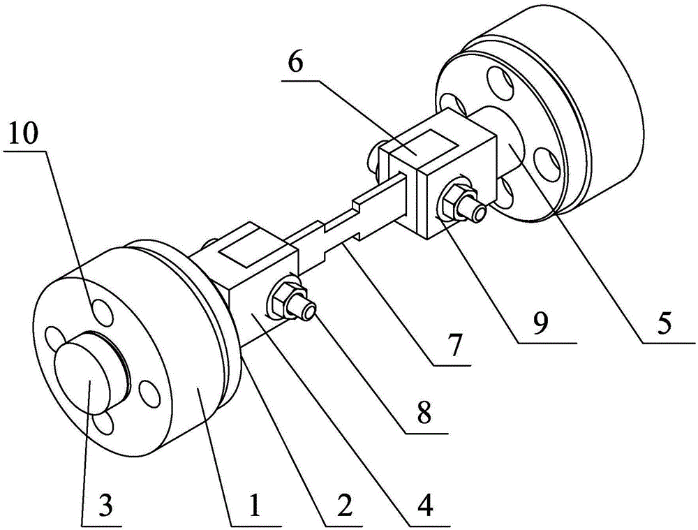
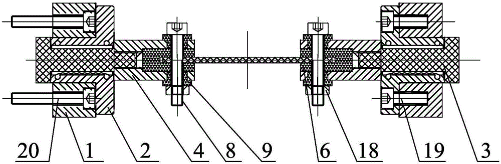
[0052] The maximum tensile force of the DIL805A / D deformation thermal expansion phase change meter is 10kN. The main structure of the DIL805A / D deformation thermal expansion phase change meter includes a sample chamber, a displacement sensor and a ejector rod that is in direct contact with the tensile sample, and the ejector rod is a phas...


PUM

PropertyMeasurementUnit
thermal conductivityaaaaaaaaaa

Abstract

The invention provides a method for improving temperature gradient in a high-temperature tension sample of a heat expansion phase change instrument. The method is characterized in that one of following methods is improved in the tension test process: a clamp is prepared from austenitic stainless steel to replace the existing clamp to test; or, a U-shaped heat isolation sleeve and a fixed screw heat isolation ring are arranged at the contact part of the sample clamping end and the clamp to completely isolate the clamp, the fixed screw and the tension sample through the U-shaped heat insulation sleeve and the fixed screw heat isolation ring, and the clamp is prepared from austenitic stainless steel to replace the existing clamp to test. The method has the advantages that the austenitic stainless steel is used as the clamp preparation material and the ceramic fiber sheet is used as the heat isolation sleeve and the heat isolation sleeve, so that the heat radiation and heat conduction of high-temperature objects and low-temperature objects are effectively inhibited; the operation is easy, the detachment and installation of the sample are convenient, and the material stability is guaranteed.

Description

technical field [0001] The invention belongs to the technical field of tensile mechanical performance testing, and in particular relates to an improved method for the temperature gradient existing in a high-temperature tensile sample of a thermal expansion phase transition instrument. Background technique [0002] During the process of heating, heat preservation and cooling, steel materials undergo phase changes, which cause their volume to expand or contract. The deformation thermal expansion phase change instrument is a device that detects the change in the length direction caused by the phase change of the material, and combines the known solid-state phase change knowledge to determine the actual temperature and time of the phase change. This equipment has important guiding significance for designing materials, measuring various performance indicators of materials, as well as simulating heat treatment process and development of follow-up product process. [0003] The str...

Claims


Application Information

Patent Timeline
Patent Type & Authority Applications(China)
IPC IPC(8): G01N3/04G01N3/18
CPCG01N3/04G01N3/18G01N2203/0017G01N2203/0226G01N2203/0458
Inventor 薛文颖刘连骞候泽然杜鹏举邓彪陈杉顾兴利
Owner NORTHEASTERN UNIV
Why Eureka
Try Eureka