Solid particle heat exchanger

A solid powder, heat exchanger technology, applied in the direction of heat exchanger types, indirect heat exchangers, heat exchange equipment, etc., can solve the problems of poor technical and economic indicators, easy wear and tear of heat exchangers, and large power consumption, and achieve good results. Energy saving effect, improved heat exchange efficiency, less power consumption effect

Active Publication Date: 2012-01-18
NANJING HUADIAN ENERGY SAVING & ENVIRONMENTAL PROTECTION EQUIP
View PDF6 Cites 16 Cited by
  • Summary
  • Abstract
  • Description
  • Claims
  • Application Information

AI Technical Summary

Problems solved by technology

[0005] However, the fluidized bed heat exchanger has the following problems: it needs to provide high-flux fluidized air, and the power consumption is large; the fluidized solid particles are easy to cause dust pollution, and a dust removal system needs to be added when the air is discharged; the fluidized solid particles and The high-frequency collision of the heat exchanger makes the heat exchanger easy to wear; in addition, it cannot handle the solid powder that chemically reacts with the air
[0007] However, the rotary cooler has the following problems: complex equipment structure, difficult maintenance, large floor area, high power consumption and equipment cost, poor technical and economic indicators, and the problem of secondary pollution
However, the heat exchanger still has the following problems: when the solid powder material collides with the tubular heat exchange body, the exchange body will vibrate, resulting in increased wear and reduced equipment life; when the solid powder material falls, the distribution is uneven and the flow rate It is uncontrollable, it is difficult to ensure sufficient heat transfer, and it is difficult to control the temperature of the material discharge. If the temperature of the material discharge is to be controlled within a certain range, it is necessary to pass through the heat exchanger multiple times, or the materials of several heat exchangers The inlet and outlet are connected in series, so that the material passes through multiple heat exchangers at one time, but whether it passes through the same heat exchanger multiple times or through multiple series heat exchangers at one time, it will increase the process and increase the cost; in addition, the solid powder material Uneven distribution during falling will also lead to uneven heat transfer, causing local overheating or overcooling of the cooling water in the heat exchange tube, so that the temperature of the cooling water outlet will inevitably fluctuate, making it difficult to directly use

Method used


Image

  • Solid particle heat exchanger
  • Solid particle heat exchanger
  • Solid particle heat exchanger

Examples


Embodiment 1

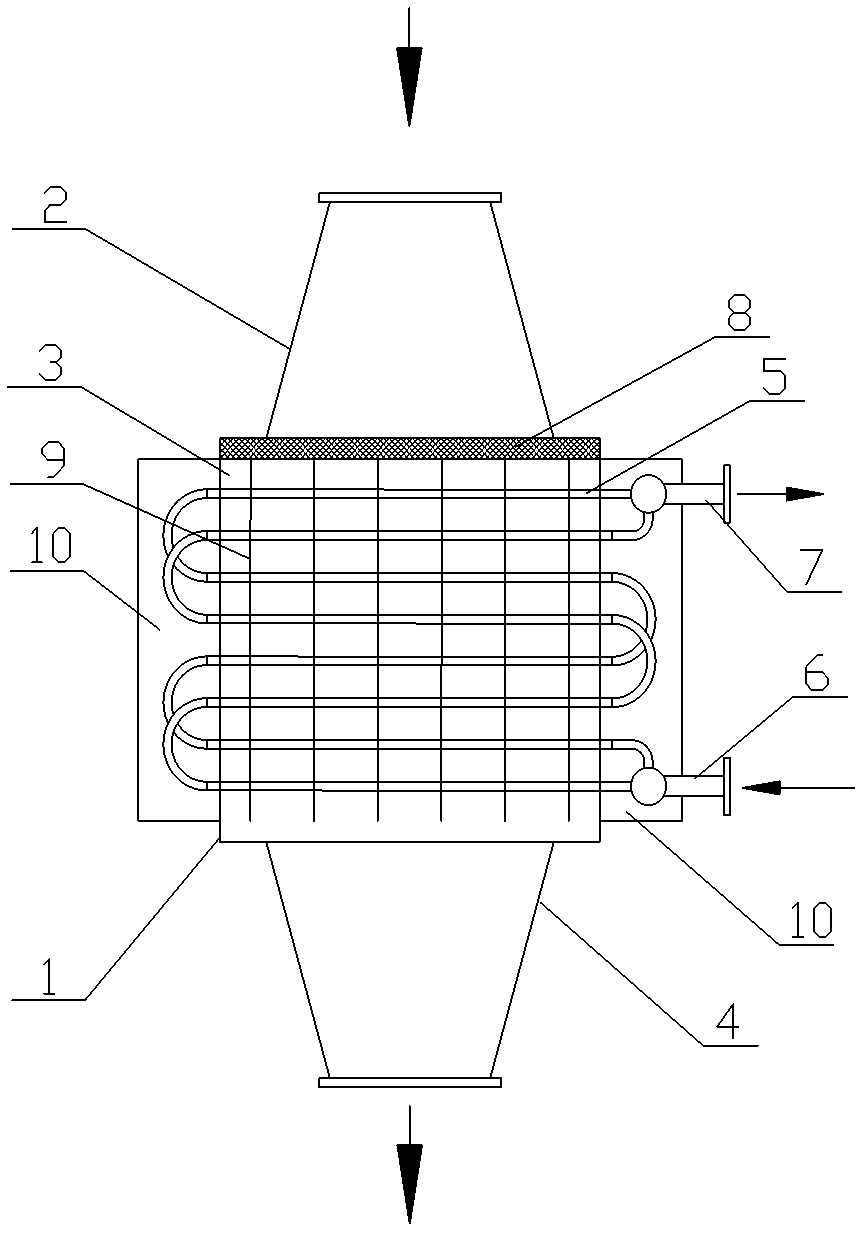
[0040] The basic structure of the solid powder heat exchanger in this embodiment is as follows: figure 1 As shown, it includes a cylindrical shell 1. The top of the shell 1 has an upper connection box 2 for receiving powder particles, a heat exchange chamber 3 in the middle, and a lower connection box 4 for discharging powder particles at the bottom. The heat exchange chamber 3 is equipped with a heat exchange tube bundle. 5. The heat exchange tube bundle 5 is provided with a fluid inlet 6 and a fluid outlet 7 on the shell 1, and the fluid inlet 6 is externally connected to a heat transfer fluid source; a distributor 8 is provided between the upper connection box 2 and the heat exchange chamber 3 .

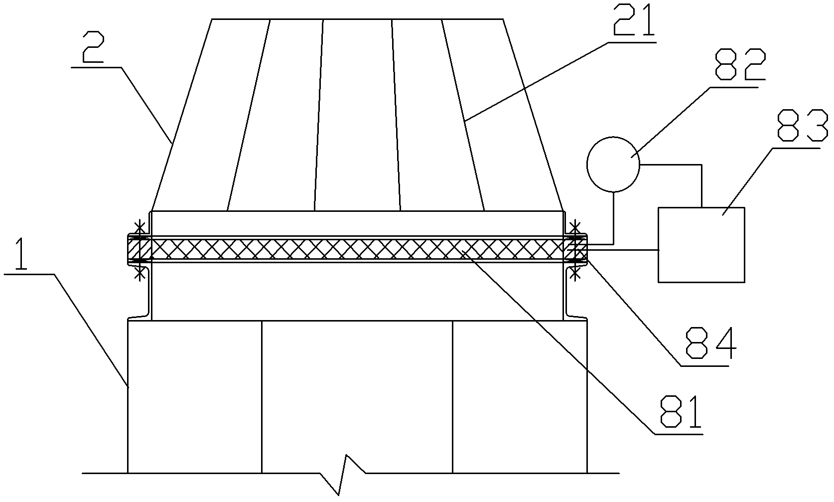
[0041] Such as figure 2 As shown, the dispenser 8 includes a silk screen layer 81, and the silk screen layer 81 is connected with the control device; connection, the sensing end of the weight sensor 82 and the output end of the vibrator 83 are connected to the silk screen layer ...

Embodiment 2

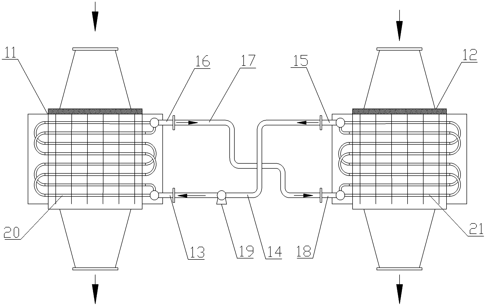
[0050] This embodiment is a solid powder heat exchange system using the solid powder heat exchanger in Embodiment 1, including a first solid powder heat exchanger 11 for cooling powder, a second solid powder heat exchanger for heating powder Heat exchanger 12; the fluid inlet 13 of the first solid powder heat exchanger 11 communicates with the fluid outlet 15 of the second solid powder heat exchanger 12 through the first pipeline 14, and the fluid of the first solid powder heat exchanger 11 The outlet 16 communicates with the fluid inlet 18 of the second solid powder heat exchanger 12 through the second pipeline 17, the heat exchange tube bundle 20 of the first solid powder heat exchanger 11, the heat exchange of the second solid powder heat exchanger 12 The tube bundle 21 , the first pipeline 14 and the second pipeline 17 form a fluid circulation loop; the fluid circulation loop is filled with heat transfer fluid; the first pipeline 14 has a fluid pump 19 .

[0051] When in u...


PUM


Abstract

The invention relates to a solid particle heater exchanger, which comprises a cylindrical shell, wherein the top of the shell is provided with an upper connecting box for receiving particles, the middle part of the shell is provided with a heat exchange chamber, the bottom of the shell is provided with a lower connecting box for discharging the particles, a heat exchange pipe bundle is arranged in the heat exchange chamber, the heat exchange pipe bundle is provided with a fluid inlet and a fluid outlet on the shell, and a heat transfer fluid source is connected to the fluid inlet; a distributor is arranged between the upper boxing box and the heat exchange chamber; the distributor comprises a silk screen layer which is connected with a control device; the control device comprises a weight inductor and a vibrator, wherein the signal output end of the weight inductor is electrically connected with the controlled end of the vibrator, and the inducting end of the weight inductor and the output end of the vibrator are respectively connected with the silk screen layer. The invention also relates to a solid particle heat exchange system adopting the solid particle heat exchanger. According to the invention, sufficient heat transfer can be ensured, the particle discharge temperature can be controlled to meet the requirements, the discharging temperature of the heat transfer fluid can be ensured to be basically constant, and favorable energy-saving effect is achieved.

Description

technical field [0001] The invention relates to a heat exchanger, in particular to a solid powder heat exchanger, belonging to the technical field of energy saving and environmental protection. Background technique [0002] As far as the applicant knows, in industrial production, solid powder is not only an important raw material, but also an important product, and it is often necessary to heat or cool a large amount of solid powder materials. For example: during the casting process, the temperature of the high-temperature molding sand poured from the mold is about 500-600°C. If it is directly air-cooled, it will waste a lot of heat and cause thermal pollution to the environment. The high-temperature hot molding sand particles must be cooled to recover waste heat; In urea production, the discharge temperature of urea granules is about 70°C. When the temperature is higher than 45°C, the packaging and storage of urea granules will cause moisture absorption, agglomeration and p...

Claims


Application Information

Patent Timeline
Patent Type & Authority Applications(China)
IPC IPC(8): F28D7/08F28F27/00
Inventor 谈双根李菊香刘小平张素军陆建宁董人和
Owner NANJING HUADIAN ENERGY SAVING & ENVIRONMENTAL PROTECTION EQUIP
Why Eureka
Try Eureka