A symmetrical bubbling plate heat transfer element

A heat transfer element and bubbling technology, applied in the direction of laminated elements, fixed plate conduit assemblies, indirect heat exchangers, etc. Cleaning process, good comprehensive performance, and the effect of enhancing pressure resistance

Active Publication Date: 2021-02-12
XI AN JIAOTONG UNIV
View PDF6 Cites 0 Cited by
  • Summary
  • Abstract
  • Description
  • Claims
  • Application Information

AI Technical Summary

Problems solved by technology

[0005] The purpose of the present invention is to provide a symmetrical bubbling plate heat transfer element to solve the problem of narrow bends in the heat exchanger channel in the prior art, easy scaling, blockage, complicated physical cleaning, high flow resistance, and is not suitable for high viscosity, Easy scaling, impurities and other working fluid problems

Method used


Image

  • A symmetrical bubbling plate heat transfer element
  • A symmetrical bubbling plate heat transfer element
  • A symmetrical bubbling plate heat transfer element

Examples


Embodiment approach

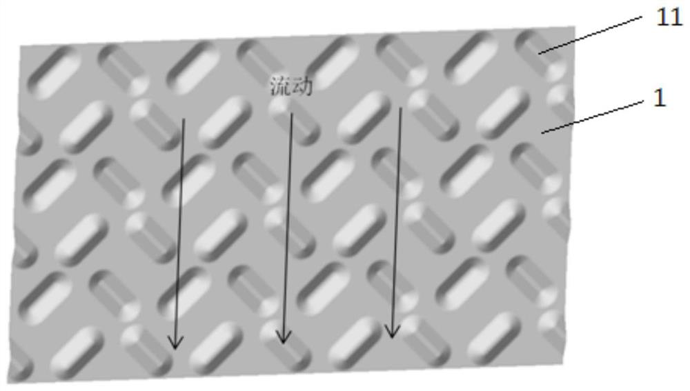
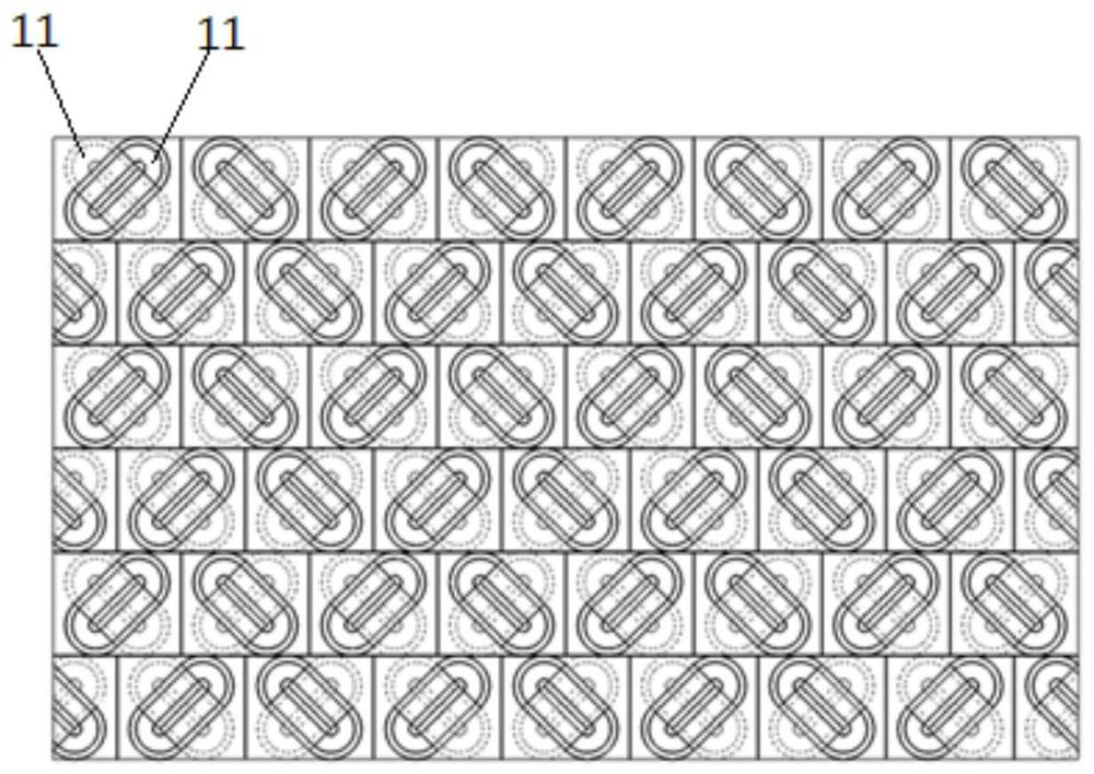
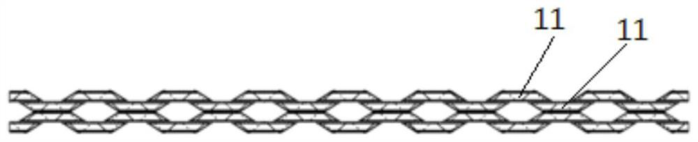
[0029]Seefigure 1 withfigure 2 , A symmetrical bubbling plate heat transfer element, comprising two or more heat exchange plates 1 superimposed on each other. Both sides of the heat exchange plate 1 are pressed with bubbling convex bodies 11, the convex bodies and The angle of the main flow direction of the fluid is 45°, and the adjacent convex bodies on one side of the heat exchange plate are symmetrical. The convex bodies 11 on the adjacent heat exchange plates 1 contact and support each other to form a plate-shaped corrugated channel. The arrangement directions of the mutually contacting convex bodies are perpendicular to each other. The adjacent convex bodies 11 on one side of the same heat exchange plate 1 form a direct fluid flow. Area. . Further, the protrusions 11 have the same size.

[0030]Further, the length of the convex body 11 is 10-30 mm, the width of the convex body 11 is 5-20 mm, and the height of the convex body 11 is 1-5 mm.

[0031]Further, the distance between adjacen...


PUM


Abstract

The invention discloses a symmetrical bubbling plate heat transfer element, which comprises two or more superimposed heat exchanging plates, both sides of the heat exchanging plates are pressed with bubbling convex bodies, and the convex bodies and The included angle of the main flow direction of the fluid is 45°, and the adjacent convex bodies on one side of the heat exchange plate are symmetrical. The protrusions on adjacent heat exchange plates support each other to form channels, and the protrusions in contact with each other are vertical. The gaps between convex bodies form large straight-through area fluid channels, which are suitable for media that are prone to scaling, high viscosity coefficient, and low flow pressure. High-pressure water can be used to directly rewash the channels, which simplifies the physical cleaning process. The invention has small flow resistance, higher overall heat transfer efficiency, good overall performance and broad application prospects.

Description

Technical field[0001]The invention belongs to the technical field of heat exchange devices, and specifically relates to a symmetrical bubbling plate type heat transfer element.Background technique[0002]Heat exchangers are the main equipment for the development and utilization of secondary energy sources, waste heat recovery, energy saving and emission reduction, and are widely used in petroleum, chemical, electric power, refrigeration, ships, vehicles, heating and other fields. Traditional shell-and-tube heat exchangers have been widely used due to their good operational stability. However, due to structural constraints, shell-and-tube heat exchangers have high cost, weight and volume, and are difficult to use for those that require weight and volume. Application occasions.[0003]Compared with traditional shell-and-tube heat exchangers, plate heat exchangers have the advantages of high heat exchange efficiency, compact and lightweight structure, small footprint, and long service life...

Claims


Application Information

Patent Timeline
Patent Type & Authority Patents(China)
IPC IPC(8): F28D9/00F28F3/04F28F3/08
CPCF28D9/0037F28F3/044F28F3/08
Inventor 白博峰蒋琛周文学张延丰
Owner XI AN JIAOTONG UNIV
Why Eureka
Try Eureka