
Air distribution gear and air automatic collection system comprising air distribution gear

An automatic collection and air technology, applied in control/regulation systems, electrical components, mechanical equipment, etc., can solve problems such as high human input, inability to assign responsibility to people, and no continuous monitoring, and achieve improved fault resistance and high positioning accuracy. , to ensure the effect of accuracy

Inactive Publication Date: 2019-12-03
CHONGQING YIXI BRAND PLANNING CO LTD
View PDF0 Cites 5 Cited by
  • Summary
  • Abstract
  • Description
  • Claims
  • Application Information

AI Technical Summary

Problems solved by technology

[0004] However, sampling by UAVs requires manual full-time control, and UAVs have a short battery life. Currently, the general battery life is 30-200 minutes, which makes UAVs in some areas that cannot be charged in time become tasteless
Moreover, the current air monitoring is divided into regular or irregular monitoring, and there is no continuous monitoring. This method makes it impossible for managers to truly obtain continuous changes in air quality, which leads to subsequent problems that cannot be held accountable.
However, once the continuous monitoring method is adopted, it will inevitably result in high manpower input, which is not in line with the current basic national conditions
[0005] In addition, the current UAV sampling can only perform single-point sampling, that is, it only carries a sampling airbag, takes off to the designated location for sampling, and then flies back to the author's location
This method makes it impossible to realize remote control of the current UAV sampling, because generally multi-point sampling is required, which requires the author to continuously disassemble and assemble the sampling airbag

Method used


Image

  • Air distribution gear and air automatic collection system comprising air distribution gear
  • Air distribution gear and air automatic collection system comprising air distribution gear
  • Air distribution gear and air automatic collection system comprising air distribution gear

Examples


Embodiment Construction

[0044] The following will clearly and completely describe the technical solutions in the embodiments of the present invention with reference to the drawings in the embodiments of the present invention.

[0045] In describing the present invention, it should be understood that the terms "upper", "lower", "front", "rear", "left", "right", "top", "bottom", "inner", " The orientation or positional relationship indicated by "outside", etc. is based on the orientation or positional relationship shown in the drawings, and is only for the convenience of describing the present invention and simplifying the description, rather than indicating or implying that the referred device or element must have a specific orientation, so as to Specific orientation configurations and operations, therefore, are not to be construed as limitations on the invention.

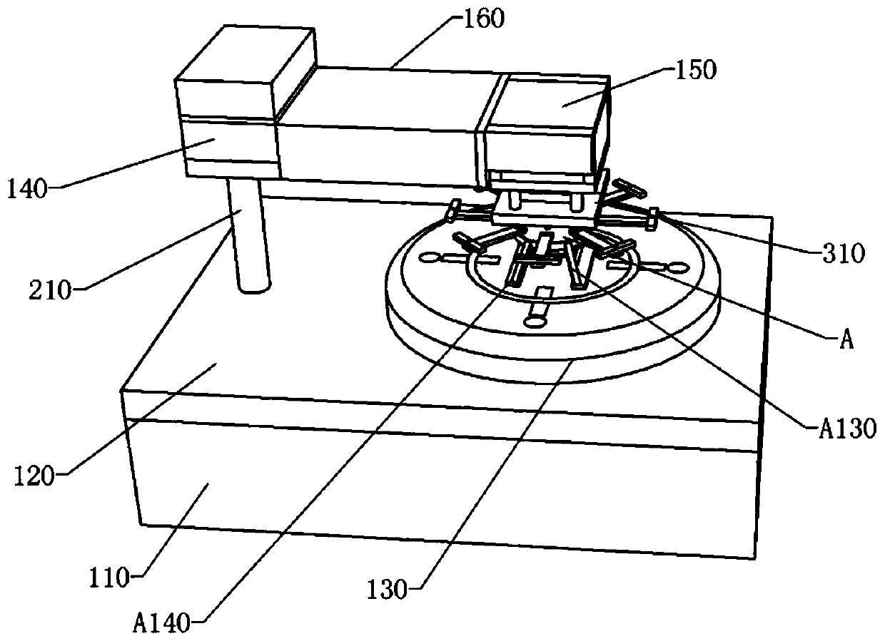
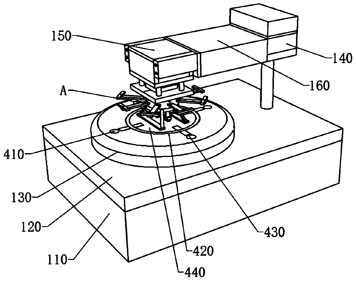
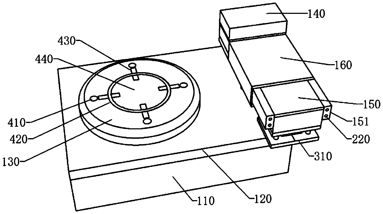
[0046] see Figure 1-Figure 27 , the air automatic collection system of this embodiment includes a charging module, an unmanned aerial v...


PUM


Abstract

The invention discloses an air distribution gear and an air automatic collection system comprising the air distribution gear. The air distribution gear is installed on an air distribution plate and isused for controlling on / off of a general air path and each branch air pipe. The air distribution gear comprises a reversing valve block installed in a reversing slot, and the reversing slot is formedin the air distribution plate; the reversing valve block is provided with a reversing notch slot and a communicating air hole; the top of the reversing valve block is assembled and fixed to one end of a valve rod, the other end of the valve rod is installed in a switching installation slot, and a maintaining sliding plate is fixed to the end, installed in the switching installation slot, of the valve rod; the valve rod can slide in an axial direction, and a valve rod compressed spring is installed on the part, located between the maintaining sliding plate and the bottom face of the inner sideof the switching installation slot, of the valve rod in a sleeving mode; and in an initial state, the reversing valve block is located at the most top of the reversing slot, the branch air pipes communicate with the general air path through the reversing notch slot, the communicating air hole in the reversing valve block is installed in the top of the reversing slot, so that the two ends of the communicating air hole are sealed by the inner wall of the reversing slot, and the space between the general air path in the part and a general air path in a next reversing slot is broken by the reversing valve block.

Description

technical field [0001] The invention relates to air sampling technology, in particular to an air distribution mechanism and an automatic air collection system thereof. Background technique [0002] With the deepening of the concept of environmental protection and the increasingly stringent environmental regulations, the monitoring of air quality has become a very necessary means. Especially in some areas where heavy industries gather, most of them require regular air sampling and analysis to obtain air monitoring data, thereby assisting the government in supervision and adjustment. [0003] The current air sampling method is mainly carried out in a fully manual or semi-manual way. The fully manual method is mainly to go to the monitoring area to use air sampling equipment for air sampling. This method is very troublesome, time-consuming and labor-intensive, and the sampling height is limited. Ground height influences, therefore, air sampling is incomplete and cannot reflect...

Claims


Application Information

Patent Timeline
Patent Type & Authority Applications(China)
IPC IPC(8): G01N1/24G05D1/08G05D1/10B64D47/00F16K11/18H02J50/20
CPCB64D47/00F16K11/18G01N1/24G05D1/0808G05D1/101H02J50/20
Inventor 袁素
Owner CHONGQING YIXI BRAND PLANNING CO LTD
Learn More