

Optical fiber shearing tool and operating method
A technology for optical cables and tools, which is applied in the field of auxiliary tools for laying optical cables, can solve problems such as low work efficiency, high labor intensity of operators, and inability to perform manual work for a long time, so as to reduce labor intensity and improve work efficiency
- Summary
- Abstract
- Description
- Claims
- Application Information
AI Technical Summary
Problems solved by technology
Method used
Image

Examples
Embodiment 1
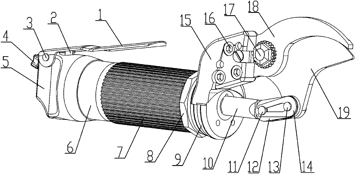
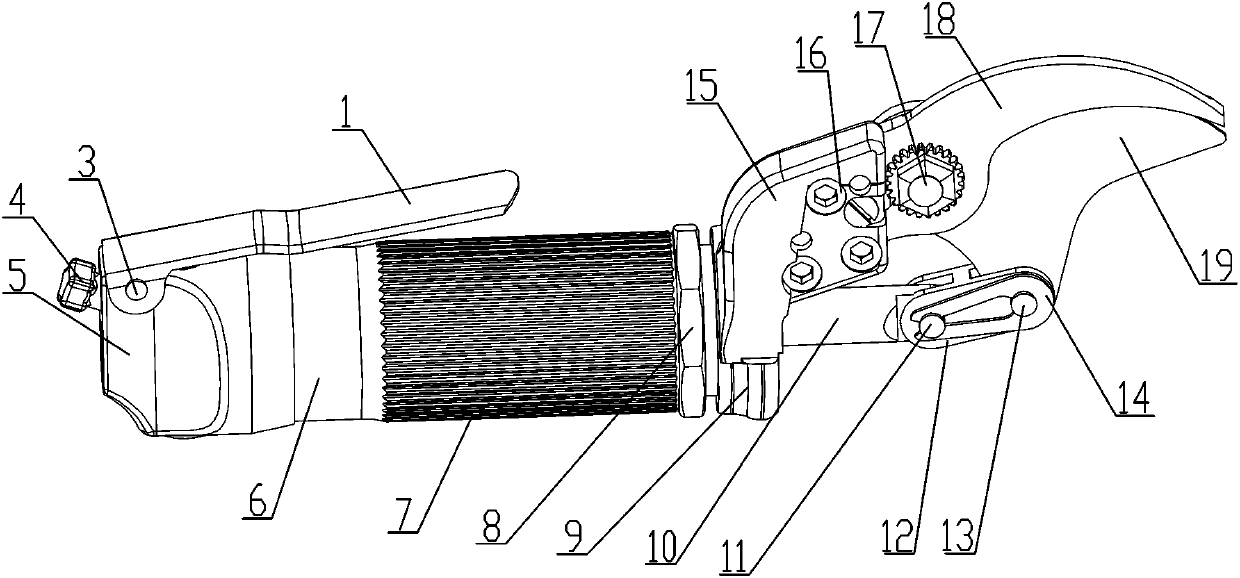
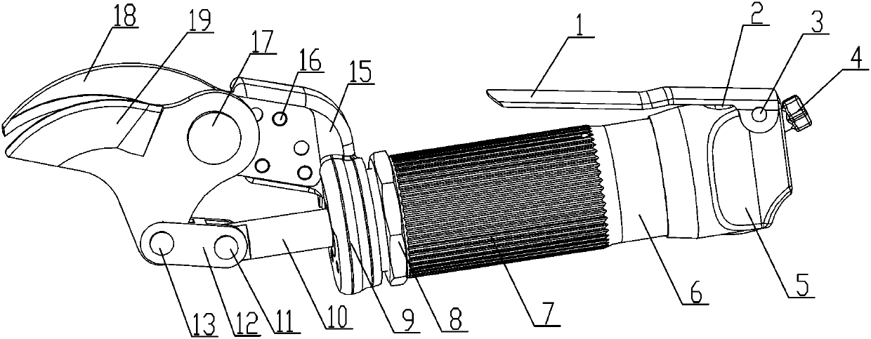
[0034] see Figure 1-5 , an optical cable cutting tool, which includes a hand-held cylinder 6, a tailstock 5 is fixedly installed at the tail of the hand-held cylinder 6, and an end cap 9 is locked and fixed at its head by a round nut 8, and the handle of the hand-held cylinder 6 A piston cavity 28 is arranged inside, and a piston body 30 is installed inside the piston cavity 28 through a sliding fit, and the piston body 30 is fixedly connected with a piston rod 36 arranged inside the piston cavity 28, and the piston rod 36 The other end is connected with a push rod 10, and the push rod 10 passes through the end cover 9, and the push rod 10 is hingedly connected with the bottom end of the movable blade 19 through a linkage mechanism, and the movable blade 19 is hinged on the fixed blade through a rotating shaft 17. 18, the two cooperate and realize cutting, the fixed blade 18 is fixedly installed on the blade mounting seat 15 through the blade fixing bolt 16, and the blade mou...
Embodiment 2
[0045] The operation method of the optical cable cutting tool comprises the following steps:
[0046] Step1: connect the air pipe of the high-pressure air source to the air pipe connection hole 22, and at this time, the plugging column 24 of the control valve stem 2 is matched with the air inlet hole 23, and is blocked;
[0047] Step2: set the optical cable to be cut between the movable blade 19 and the fixed blade 18;
[0048] Step3: When cutting is required, manually press the pressure plate 1, press down the control valve stem 2 through the pressure plate 1, at this time the plugging column 24 will go down, and the air intake hole 23 will be leaked at this time, and the high-pressure gas will pass through the air intake hole 23 Enter the bottom cylindrical hole 25, and then enter the piston cavity 28 through the piston barrel air inlet 27, at this time, the high-pressure gas will push the piston body 30, and then push the piston rod 36 through the piston body 30;
[0049] ...
PUM
 Abstract
Description
Claims
Application Information