Liquid crystal display device and HUD (head up display) system
A liquid crystal display device, head-up display system technology, applied in optics, instruments, nonlinear optics, etc., can solve the problem of heating of display modules, and achieve the effect of solving easy heating and enhancing image brightness
- Summary
- Abstract
- Description
- Claims
- Application Information
AI Technical Summary
Problems solved by technology
Method used
Image

Examples
Embodiment 1
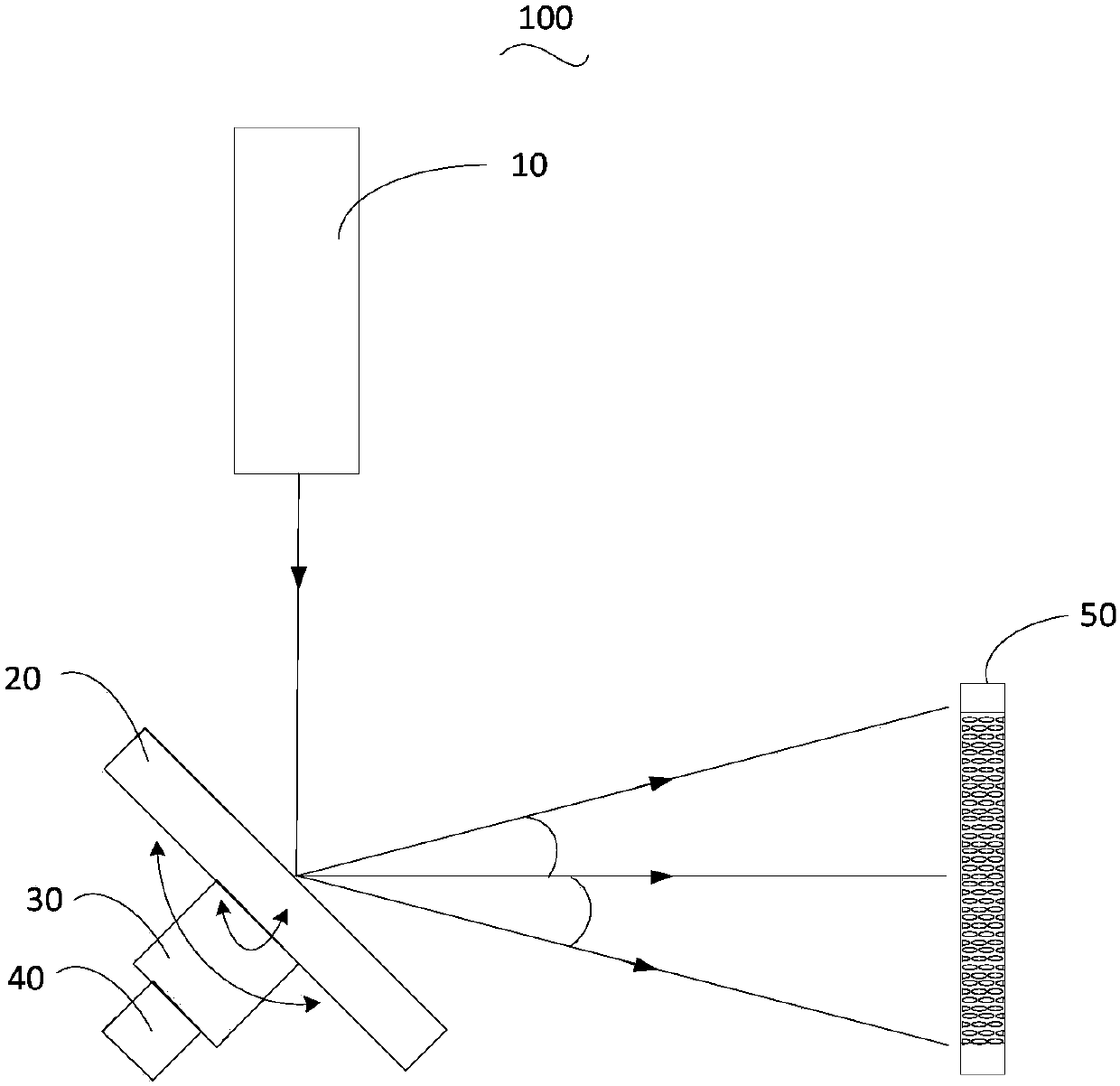
[0036] see figure 1 , is a schematic structural diagram of a liquid crystal display device provided by one embodiment of the present invention. Such as figure 1 As shown, the liquid crystal display device 100 includes a laser light source 10 , a mirror 20 , a driving device 30 , a controller 40 and a display module 50 .
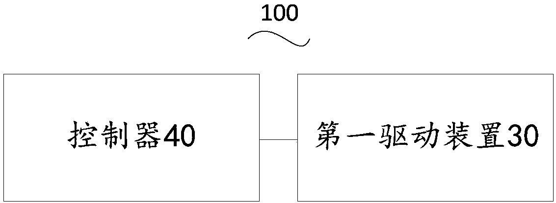
[0037] The drive device 30 is connected to the reflector 20 , the controller 40 is connected to the drive device 30 , and the reflector 20 is arranged between the laser light source 10 and the display module 50 . The laser light source 10 is used to emit a laser beam, the mirror 20 is used to receive and reflect the laser beam to the display module 50, and the controller 40 is used to control the driving device 30 to drive the mirror 20 to move, so that the laser beam reflected by the mirror 20 Covering the entire back of the display module 50 to provide a backlight for the display module 50 .
[0038] Specifically, the laser light source 10 may include a ...
Embodiment 2
[0051] see Figure 5 , is a schematic structural diagram of a liquid crystal display device provided by another embodiment of the present invention. Such as Figure 5 As shown, the liquid crystal display device 100 includes a laser light source 10 , a beam coupler 11 , an optical fiber 12 , an optical fiber collimator 13 , a mirror 20 , a driving device 30 , a controller 40 and a display module 50 .
[0052] Wherein, the structures of the laser light source 10 , the reflector 20 , the driving device 30 , the controller 40 and the display module 50 are the same as those in the first embodiment, and will not be repeated here.
[0053] The beam coupler 11 , the optical fiber 12 and the optical fiber collimator 13 are arranged between the laser light source 10 and the reflector 20 . Specifically, the beam coupler 11 is capable of combining or splitting the laser beams. In this embodiment, the beam coupler 11 is connected to the laser light source 10, specifically, it can be arr...
Embodiment 3
[0059] see Image 6 , is a schematic structural diagram of a liquid crystal display device provided by another embodiment of the present invention. Such as Image 6 As shown, the liquid crystal display device 100 includes a laser light source 10 , a mirror 20 , a driving device 60 , a controller 40 and a display module 50 .
[0060] Wherein, the structure of the laser light source 10 , the reflector 20 , the controller 40 and the display module 50 is the same as that in the first embodiment, and will not be repeated here.
[0061] Please also refer to Figure 7 , the driving device 60 includes a rotation unit 61 and a translation unit 62 . The rotation unit 61 is connected with the mirror 20 , the translation unit 62 is connected with the laser light source 10 and the reflection mirror 20 respectively, and both the rotation unit 61 and the translation unit 62 are connected with the controller 40 . The rotating unit 61 is used to drive the mirror 20 to rotate relative to th...
PUM
 Abstract
Description
Claims
Application Information
 - R&D
- Intellectual Property
- Life Sciences
- Materials
- Tech Scout
- Unparalleled Data Quality
- Higher Quality Content
- 60% Fewer Hallucinations
Browse by: Latest US Patents, China's latest patents, Technical Efficacy Thesaurus, Application Domain, Technology Topic, Popular Technical Reports.
© 2025 PatSnap. All rights reserved.Legal|Privacy policy|Modern Slavery Act Transparency Statement|Sitemap|About US| Contact US: help@patsnap.com