
Method for optimizing structure of fuel cell multi-stack distribution cavity based on fluent simulation

A fuel cell and inner cavity technology, applied in the direction of fuel cells, fuel cell additives, fuel cell control, etc., to achieve the effects of improving fluid uniformity, reducing backflow, and reducing pressure loss

Active Publication Date: 2019-12-03
WUHAN HYDRAV FUEL CELL TECH CO LTD
View PDF6 Cites 6 Cited by
  • Summary
  • Abstract
  • Description
  • Claims
  • Application Information

AI Technical Summary

Problems solved by technology

[0003] The present invention provides a method for optimizing the internal cavity structure of multi-stack distribution of fuel cells based on fluent simulation. Aiming at a complex flow path with a circular inlet and multi-branched pipe with a square outlet, the deficiencies in the structure are found out through fluent analysis and optimized to achieve Reduced pressure drop and increased outlet flow uniformity, with the goal of improving system performance and stability

Method used


Image

  • Method for optimizing structure of fuel cell multi-stack distribution cavity based on fluent simulation
  • Method for optimizing structure of fuel cell multi-stack distribution cavity based on fluent simulation
  • Method for optimizing structure of fuel cell multi-stack distribution cavity based on fluent simulation

Examples


Embodiment Construction

[0031] The technical solutions of the present invention will be clearly and completely described below in conjunction with the accompanying drawings of the present invention. Based on the embodiments of the present invention, all other embodiments obtained by persons of ordinary skill in the art without creative efforts fall within the protection scope of the present invention.

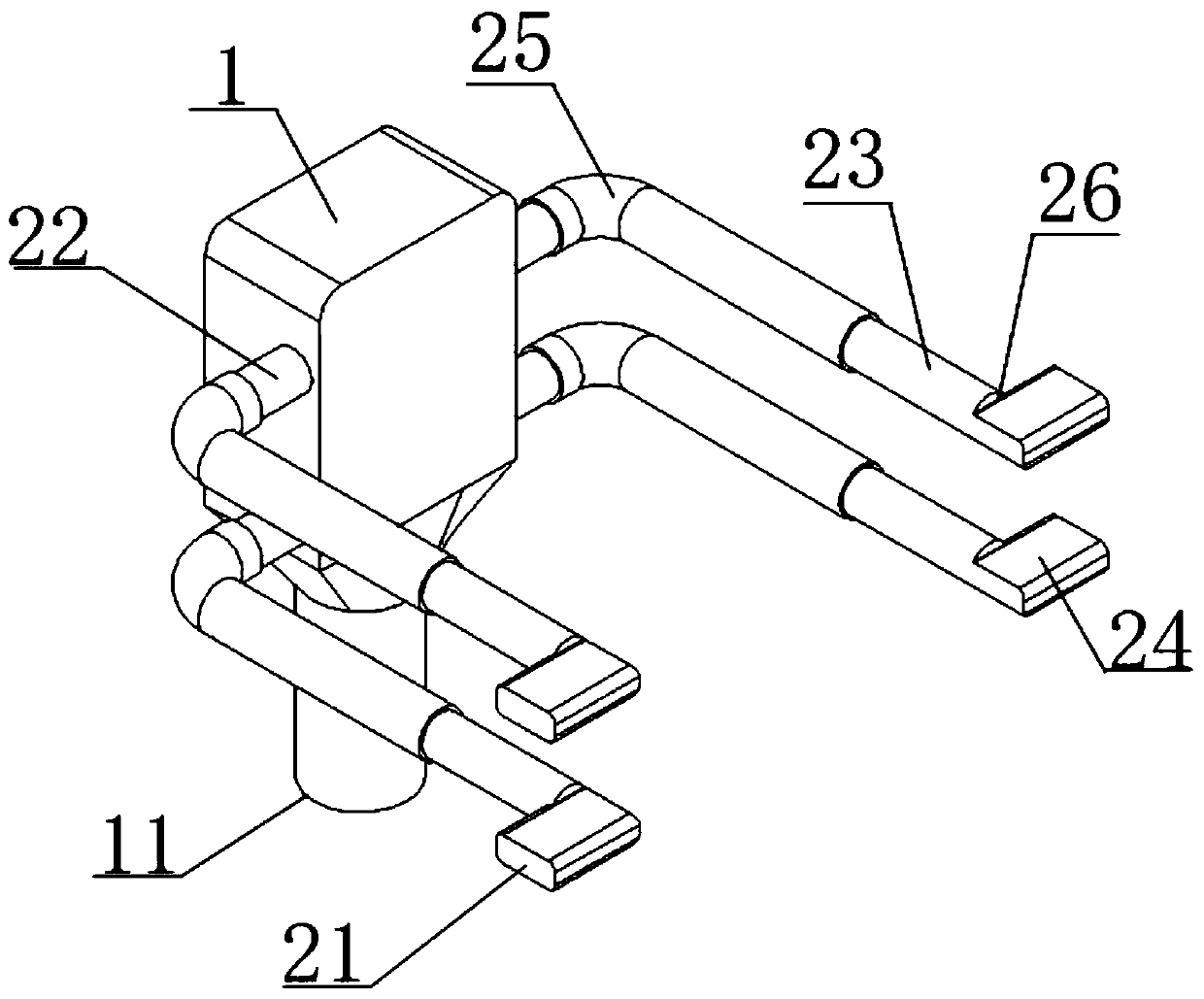
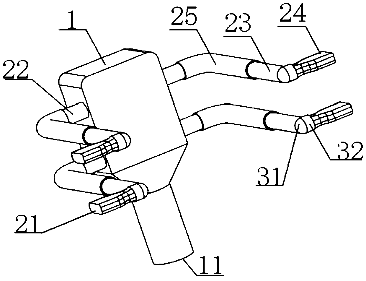
[0032] The multi-stack distribution cavity of the fuel cell uses one inlet and multiple outlets for fluid distribution. Such as figure 2 Shown is one of the existing four-stack engine distributor inner chambers, including the main chamber 1 and the Z-shaped diverter elbows symmetrically arranged on both sides of the main chamber 1, and the lower end of the main chamber 1 is a circular inlet 11 , left and right symmetrically provided with four circular outlets communicating with the shunt pipe. The Z-shaped diverter elbow includes a circular inlet and a square outlet 21, the circular inlet is connec...


PUM


Abstract

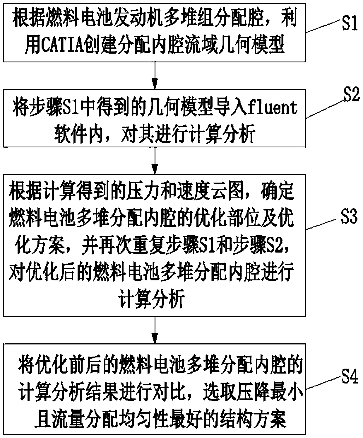
The invention discloses a method for optimizing the structure of a fuel cell multi-stack distribution cavity based on fluent simulation. The method comprises the steps that S1 CATIA is used to createa watershed geometric model of the fuel cell engine multi-stack distribution cavity; S2 the watershed geometric model is imported into fluent software, and calculated and analyzed to acquire the evenness indexes of the pressure drop of inlets and outlets, the flow rate distribution of each outlet and the flow velocity of each outlet; S3 according to the pressure and velocity cloud diagram of the calculation result, the optimal location and optimization plan are determined; step S1 and step S2 are repeated; the optimized distribution cavity is calculated and analyzed again; and S4 the calculation and analysis results of the distribution cavity before and after optimization are compared, and the structural solution with the smallest pressure drop and the best flow distribution uniformity isselected. According to the method, for a complex flow channel with circular inlets and manifold square outlets, the unreasonable part in the structure is found out and optimized through fluent calculation and analysis; the pressure drop is reduced, and the uniformity of the outlet flow is improved; and the performance and stability of the system are improved.

Description

technical field [0001] The invention relates to the field of hydrogen fuel cell engines, in particular to a method for optimizing the internal cavity structure of multi-stack distribution of fuel cells based on fluent simulation. Background technique [0002] As a zero-pollution clean energy engine, the hydrogen fuel cell engine has the advantages of zero emission, low noise, and high energy conversion efficiency. Hydrogen fuel cell engines are being continuously promoted and applied in different industries, so in order to meet different application fields, it is necessary to develop engines of different forms and powers. At present, in order to meet the requirements of high power and miniaturization, multiple electric stacks need to be combined and applied, which requires uniform distribution of fuel and coolant flow into the electric stack (including small difference in the flow rate of each single stack, and uniform flow rate at the inlet of each stack. high resistance),...

Claims


Application Information

Patent Timeline
IPC IPC(8): H01M8/04298G06F17/50
CPCH01M8/04305Y02E60/50
Inventor 谢小明董志亮胡清辉熊云江洪春于强秦连庆唐廷江
Owner WUHAN HYDRAV FUEL CELL TECH CO LTD
Learn More