Motor cooling and vibration reducing mechanism

A shock-absorbing mechanism and heat-dissipating shell technology, applied in electrical components, electromechanical devices, electric components, etc., can solve the problems of poor heat dissipation, low refrigerant fluidity, motor damage, etc., to improve the heat exchange rate and speed up the heat exchange. Efficiency, the effect of increasing the heat exchange rate

Inactive Publication Date: 2019-12-03
山东博发智能科技有限公司
View PDF11 Cites 30 Cited by
  • Summary
  • Abstract
  • Description
  • Claims
  • Application Information

AI Technical Summary

Problems solved by technology

[0003] The retrieval authorization announcement number is CN106059196B, which discloses a motor with fast heat dissipation, including a stator, a rotor sleeved in the stator, a rotating shaft pierced on the rotor, and a shell end surface that is sleeved on the stator that is adapted to each other. The casing with ventilation holes and the base with positioning and mounting hole columns in the center, the circuit board is erected on the outside of the base, the drainage fan is fixed on the outside of the end surface of the casing on the rotating shaft, and the stator is sealed with a plastic seal, and the plastic seal faces The end surface on one side of the base is integrally provided with a plastic-encapsulated reinforced connection ring that is attached to the side wall of the housing. The airflow between the bottom plate and the bottom plate is sent into the motor through the vent hole on the bottom plate, and then absorbs the heat in the motor, and then is quickly led out of the motor through the vent hole on the inclined and reinforced hole wall. Although the patent has a strong integrity of the whole motor, the structure Compact, easy to disassemble and assemble, low cost, high strength, good stability, low noise, but the heat dissipation is not good through air holes
[0004] When the existing motor works for a long time, it will generate a lot of heat and cause damage to the motor. At present, many heat dissipation methods are air-cooled or water-cooled to dissipate heat on the surface of the motor. The motor will vibrate violently and cause damage to the motor. In order to solve the above problems, we propose a motor cooling and shock absorbing mechanism

Method used


Image

  • Motor cooling and vibration reducing mechanism
  • Motor cooling and vibration reducing mechanism
  • Motor cooling and vibration reducing mechanism

Examples


Embodiment 1

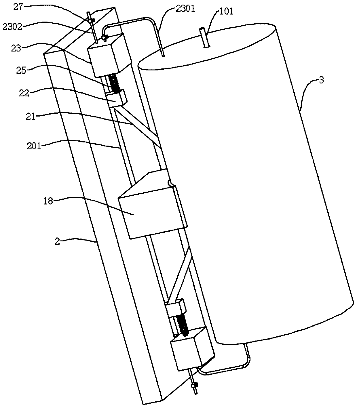
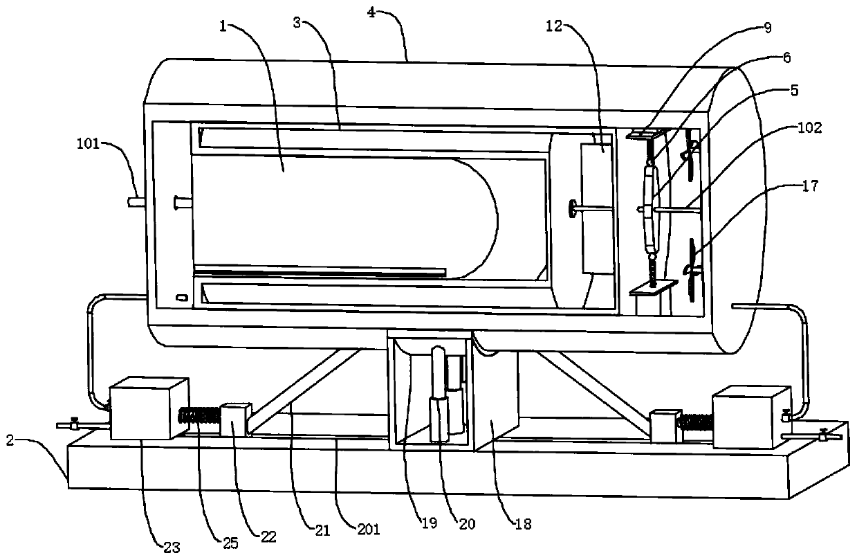
[0032] refer to Figure 1-3, a motor cooling and shock absorbing mechanism, comprising a motor body 1, a heat dissipation shell 4 and a base 2, the outer wall of the motor body 1 is fixedly connected with a heat dissipation water jacket 3, and the motor body 1 is fixedly connected to the inside of the heat dissipation casing 4 through the heat dissipation water jacket 3, The two ends of the motor body 1 are respectively fixedly connected with a first drive shaft 101 and a second drive shaft 102, one end of the first drive shaft 101 extends outward through the side wall of the heat dissipation shell 4, and one end of the second drive shaft 102 passes through the cooling water The side wall of the sleeve 3 extends to the inside of the heat dissipation shell 4, and the heat dissipation water jacket 3 is fixedly connected with a symmetrically arranged support plate 9 on the side wall inside the heat dissipation shell 4, and the side wall of the support plate 9 is fixedly connected ...

Embodiment 2

[0036] refer to Figure 4 , a motor cooling and damping mechanism, which is basically the same as Embodiment 1, the difference is that the refrigerant pumping assembly includes a liquid tank 10, and the side wall of the liquid tank 10 is slidably connected with a first slide bar 7, and the first slide bar 7 One end placed inside the liquid tank 10 is fixedly connected with a first piston plate 11, a water pipe 1001 is plugged into the side wall of the liquid tank 10, and one end of the water pipe 1001 passes through the side wall of the heat dissipation water jacket 3 and extends to the inside of the heat dissipation water jacket 3;

[0037] The reciprocating mechanism includes a two-way cam 5 and a rolling ball 6. The two-way cam 5 is connected to the second drive shaft 102 placed on the outer wall of the heat dissipation shell 4. The rolling ball 6 is fixedly connected to the end of the first slide bar 7 away from the liquid tank 10. The two-way cam 5 is offset against the r...

Embodiment 3

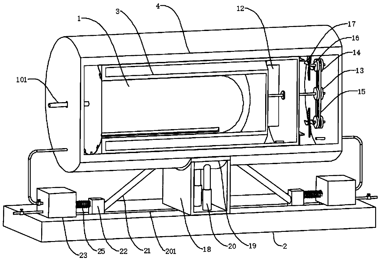
[0040] refer to Figure 2-3 , a motor cooling and shock absorbing mechanism, which is basically the same as Embodiment 2, the difference is that the heat dissipation assembly includes fan blades 17, and the fan blades 17 are movably connected to the inner wall of the heat dissipation housing 4 through the rotating rod 16, and the second drive shaft 102 A first pulley 13 is socketed on the outer wall, a second pulley 14 is socketed on the outer wall of the rotating rod 16, and the first pulley 13 and the second pulley 14 are connected by a belt 15 through transmission;

[0041] The rotation of the second drive shaft 102 will drive the first pulley 13 connected to it to rotate, and the first pulley 13 will drive the second pulley 14 to rotate through the belt 15, and the second pulley 14 will drive the rotating rod 16 to rotate to drive the fan. The leaves 17 rotate to dissipate heat inside the heat dissipation housing 4 .


PUM


Abstract

The invention discloses a motor cooling and vibration reducing mechanism, and belongs to the technical field of motors. The motor cooling and vibration reducing mechanism comprises a motor main body,a heat dissipation shell and a base, wherein the motor main body is fixedly connected to the interior of the heat dissipation shell through a heat dissipation water jacket, a refrigerant sucking and discharging assembly is fixedly connected to the side wall of a supporting plate, one end, away from a second driving shaft, of a reciprocating mechanism is connected to the refrigerant sucking and discharging assembly, one end, away from the motor main body, of the second driving shaft is connected to a heat dissipation assembly, a push rod is movably connected to the side wall, close to the base,of the heat dissipation shell, and an air diffusion assembly is connected to one end, away from the push rod, of a sliding block. According to the invention, the cooling liquid in the heat dissipation water jacket is sucked out and then pressed back through the refrigerant sucking and discharging assembly to increase the liquid flowing speed so as to improve the heat dissipation efficiency; and under the actions of the buffer assembly and the second spring of the push rod, the motor can be subjected to vibration reducing while the hot gas in the heat dissipation shell can be discharged to dissipate the heat of the motor so as to improve the heat dissipation efficiency and the vibration reducing efficiency.

Description

technical field [0001] The invention relates to the technical field of electric motors, in particular to a cooling and damping mechanism for electric motors. Background technique [0002] The motor commonly known as "motor" refers to an electromagnetic device that realizes the conversion or transmission of electric energy according to the law of electromagnetic induction. The motor is represented by the letter M (the old standard uses D) in the circuit. Its main function is to generate driving torque. The power source of electrical appliances or various machinery, the generator is represented by the letter G in the circuit, and its main function is to convert mechanical energy into electrical energy. [0003] The retrieval authorization announcement number is CN106059196B, which discloses a motor with fast heat dissipation, including a stator, a rotor sleeved in the stator, a rotating shaft pierced on the rotor, and a shell end surface that is sleeved on the stator that is a...

Claims


Application Information

Patent Timeline
Patent Type & Authority Applications(China)
IPC IPC(8): H02K5/20H02K9/19H02K9/06H02K5/24
CPCH02K5/20H02K5/24H02K9/06H02K9/19
Inventor 刘宾
Owner 山东博发智能科技有限公司
Why Eureka
Try Eureka