Line loss reference signal indication method and device, terminal, base station and storage medium

A reference signal and path loss technology, which is applied in pilot signal allocation, transmission path sub-channel allocation, signaling allocation, etc., can solve the problems of high signaling overhead, unreliable path loss measurement, and long effective time, so as to save Signaling overhead, the effect of improving configuration flexibility

Pending Publication Date: 2019-12-03
ZTE CORP
View PDF4 Cites 12 Cited by
  • Summary
  • Abstract
  • Description
  • Claims
  • Application Information

AI Technical Summary

Problems solved by technology

[0003] In the existing 5G communication system, it is required to support the uplink power control method based on beam pairs, but the flexibility of beam parameter configuration for uplink transmission is higher than that of path loss reference signal parameter configuration for uplink transmission power control, which leads to In an actual communication system, when beam switching occurs, the beam relationship of the path loss reference signal used for uplink transmission power control and the beam relationship of the target uplink transmission cannot be updated synchronously, and the path loss measurement is unreliable, which is not conducive to uplink power control; in addition, due to The configuration of path loss reference signal parameters used for uplink transmission power control is less flexible. When beam switching occurs, frequent RRC reconfiguration (Radio Resource Control Reconfiguration, RRCReconfiguration) is required, which takes a long time to take effect and has huge signaling overhead, which is not conducive to system stability

Method used


Image

  • Line loss reference signal indication method and device, terminal, base station and storage medium
  • Line loss reference signal indication method and device, terminal, base station and storage medium
  • Line loss reference signal indication method and device, terminal, base station and storage medium

Examples


Embodiment Construction

[0027] In order to make the purpose, technical solution and advantages of the present invention more clear, the embodiments of the present invention will be described in detail below in conjunction with the accompanying drawings. It should be noted that, in the case of no conflict, the embodiments in the present application and the features in the embodiments can be combined arbitrarily with each other.

[0028] The steps shown in the flowcharts of the figures may be performed in a computer system, such as a set of computer-executable instructions. Also, although a logical order is shown in the flowcharts, in some cases the steps shown or described may be performed in an order different from that shown or described herein.

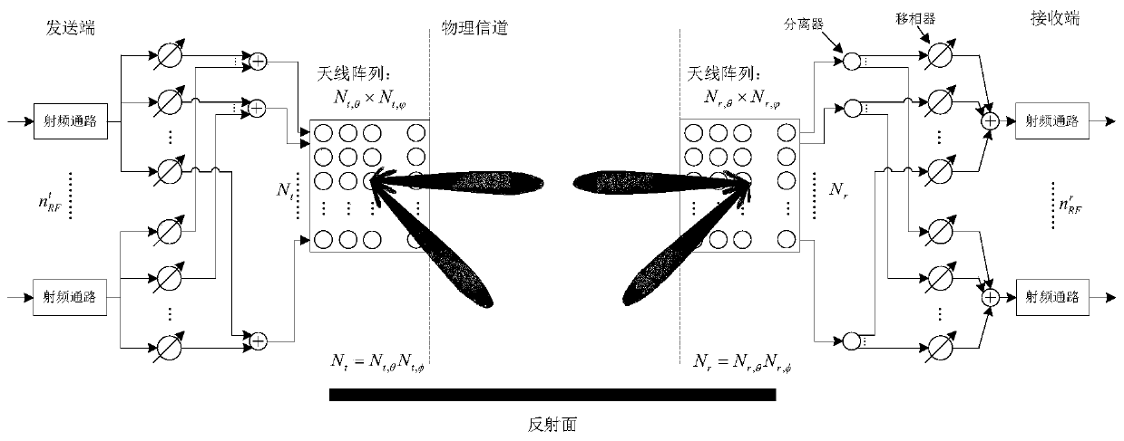
[0029] figure 1 It is a schematic structural diagram of a hybrid analog-digital beamforming transceiver adopted in the embodiment of the present application. The transmitting end and the receiving end of the transceiver system are configured with multipl...


PUM


Abstract

The invention discloses a path loss reference signal indication method and device, a terminal, a base station and a storage medium. The path loss reference signal indication method comprises the following steps: receiving an uplink transmission control signaling sent by the base station; determining an uplink transmission airspace relationship parameter according to the uplink transmission controlsignaling; and determining a path loss reference signal for uplink transmission power control according to the uplink transmission airspace relationship parameter. According to the scheme provided bythe embodiment of the invention, the path loss reference signal is determined according to the spatial domain relationship parameter, the signaling overhead is saved, and the path loss reference signal configuration flexibility of uplink transmission power control is improved.

Description

technical field [0001] Embodiments of the present invention relate to but are not limited to a method and device for indicating a path loss reference signal, a terminal, a base station, and a storage medium. Background technique [0002] The high frequency band with ultra-wide bandwidth (that is, millimeter wave communication) has become an important direction for the development of mobile communication in the future, and has attracted the attention of academic and industrial circles around the world. In particular, the advantages of millimeter waves are becoming more and more attractive in the current increasingly congested spectrum resources and massive access to physical networks. In many standard organizations, such as IEEE (Institute of Electrical and Electronics Engineers, Institute of Electrical and Electronics Engineers ), 3GPP (3rdGeneration Partnership Project, 3rd Generation Partnership Project) have launched corresponding standardization work. For example, in th...

Claims


Application Information

Patent Timeline
Patent Type & Authority Applications(China)
IPC IPC(8): H04L5/00H04W52/14H04W52/24
CPCH04L5/0053H04W52/146H04W52/242H04L5/0051
Inventor 赵嘉琦姚珂高波常虹李萍
Owner ZTE CORP
Why Eureka
Try Eureka