Staggered spraying machine and staggered spraying process

A technology of spraying machine and spraying mechanism, which is applied in the direction of coating, spraying device, and device for coating liquid on the surface, etc. It can solve the problems of difficult cleaning, workpiece pollution, and low paint recovery rate, so as to reduce pollution and increase recovery rate , reducing the effect of cleaning operations

Pending Publication Date: 2019-12-06
安徽龙马自动化科技有限公司
View PDF5 Cites 0 Cited by
  • Summary
  • Abstract
  • Description
  • Claims
  • Application Information

AI Technical Summary

Problems solved by technology

[0004] However, there are obvious defects in the above-mentioned spraying method, specifically: all the spray guns on the spraying rack move synchronously and move in unison, and the atomized paint sprayed from the spray guns generates airflow interference with each other, and one part is attached to the surface of the workpiece, and the other part It is not sucked by the air duct at the bottom of the spraying machine in time, and diffuses in the spraying room; the diffuse atomized paint is easy to adhere to the inner wall of the spraying machine due to the flow of airflow, and it is not easy to clean; the diffuse atomized paint is easy to adhere to due to the flow of airflow On the surface of the paint layer of the workpiece, the workpiece is polluted; the atomized paint is attached to the inner wall of the sprayer and the workpiece that has been sprayed, resulting in a low paint recovery rate

Method used


Image

  • Staggered spraying machine and staggered spraying process
  • Staggered spraying machine and staggered spraying process
  • Staggered spraying machine and staggered spraying process

Examples


Embodiment Construction

[0028] In order to make the objectives, technical solutions, and advantages of the present invention clearer, the following further describes the present invention in detail with reference to the accompanying drawings and embodiments. It should be understood that the specific embodiments described here are only used to explain the present invention, but not to limit the present invention.

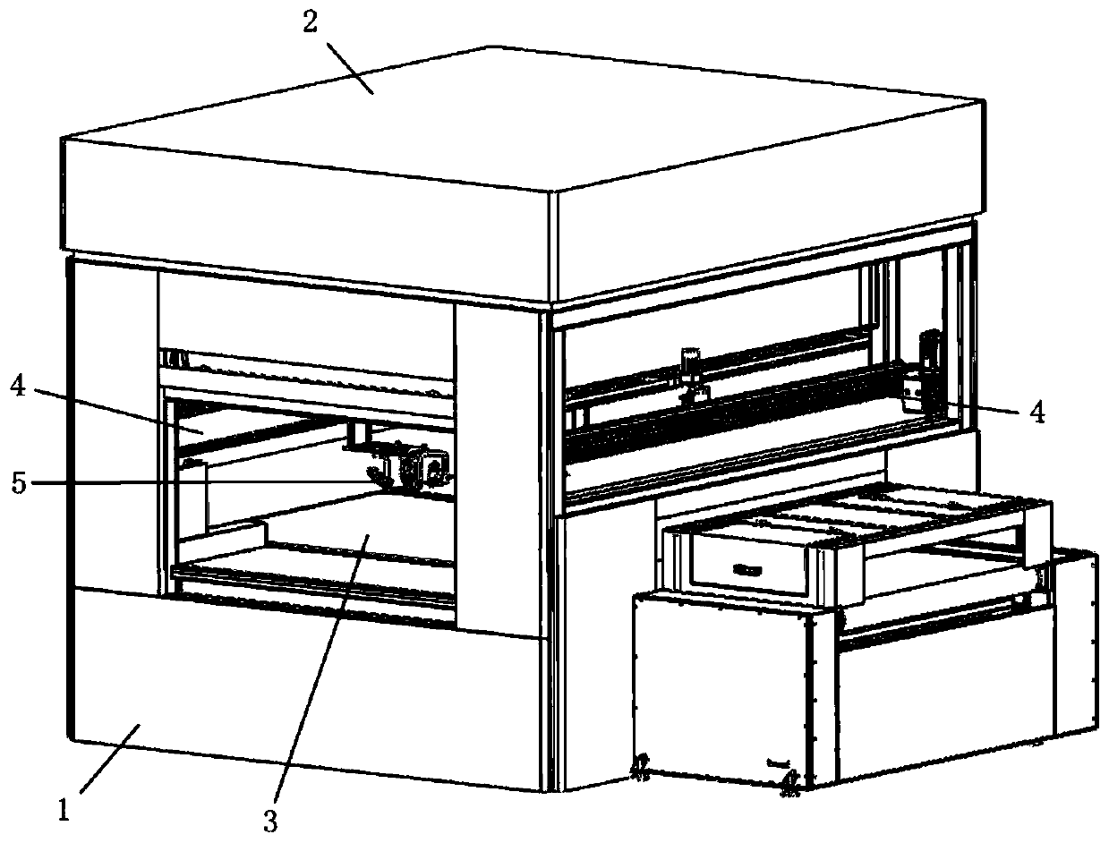
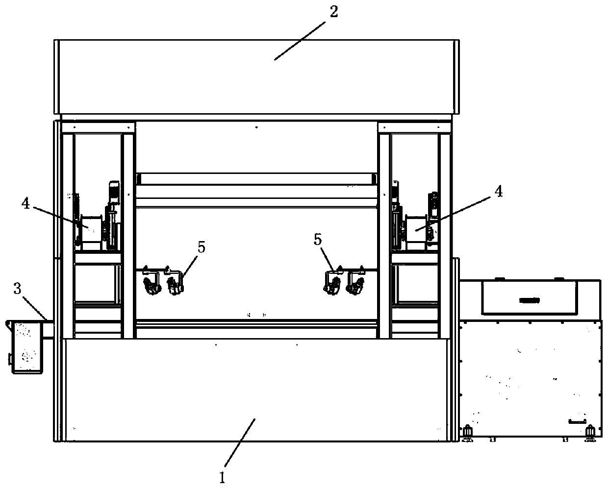
[0029] reference Figure 1 to Figure 3 , A dislocation spraying process, including the following steps:

[0030] 1. The conveyor belt 3 runs to transport the workpiece to be sprayed into the spraying room of the spraying machine;

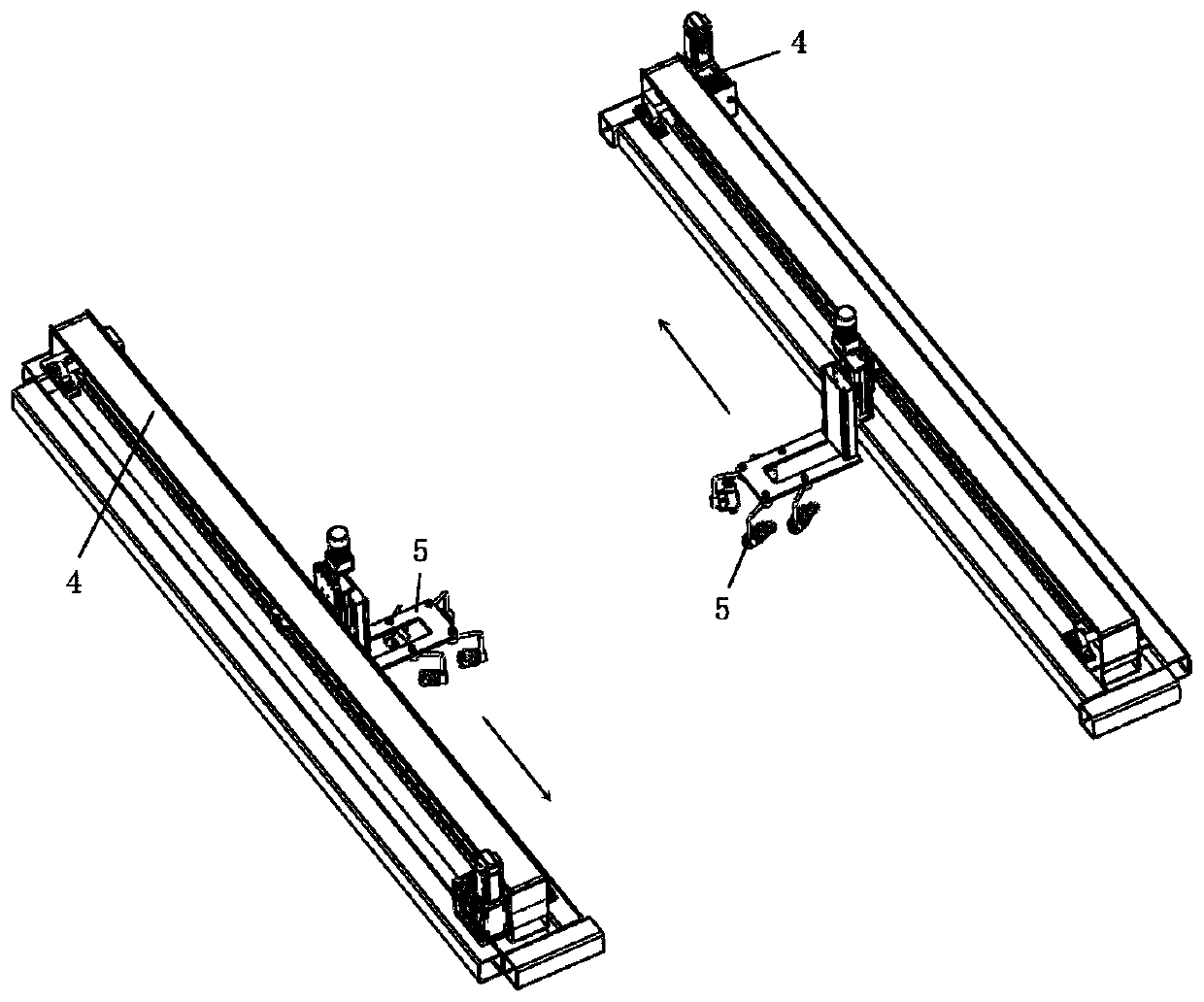
[0031] 2. The reciprocating machine 4 runs to drive the spraying mechanism 5 to move horizontally;

[0032] 3. The spray gun of spraying mechanism 5 sprays the workpiece;

[0033] During spraying, the two reciprocating machines 4 respectively drive the two spraying mechanisms 5 to move in anti-parallel, forming a staggered spray.

[0034] The lengths of the two reciprocat...


PUM


Abstract

The invention relates to a staggered spraying process. The process comprises the following steps that 1, a conveying belt works so as to convey a to-be-sprayed workpiece to a spraying chamber of a spraying machine; 2, reciprocating machines work so as to drive spraying mechanisms to horizontally move; and 3, spraying guns of the spraying mechanisms carry out spraying on the workpiece. During spraying, the two reciprocating machines drive the two spraying mechanisms to move in antiparallel directions correspondingly to form staggered spraying. The staggered spraying machine is further involved,and is applied to the staggered spraying process. According to the staggered spraying machine and the staggered spraying process, the original defect that all spray guns move together is changed, thetwo spray guns on a spray frame are moved in different directions, the interference when the spray guns spray the atomized paint out is reduced, the paint mist diffusing phenomenon in a spray chamberis reduced, the pollution to the inner wall of the spray machine and the pollution to the workpieces are reduced, and meanwhile the recovery rate of the paint is improved.

Description

Technical field [0001] The invention relates to the field of spraying, in particular to a staggered spraying machine and a staggered spraying process. Background technique [0002] The spraying machine is a special spraying equipment using high-pressure airless spraying technology. High-pressure airless spraying, also known as airless spraying, uses a high-pressure plunger pump to directly pressurize the paint to form high-pressure paint, which is sprayed out of the muzzle to form an atomized airflow to act on the surface of the object. Compared with air spraying, the paint surface is uniform and non-grainy. Due to the isolation from the air, the paint is dry and clean. Airless spraying can be used for the construction of high-viscosity paint, and the edges are clear, and it can even be used for some spraying projects with boundary requirements. [0003] The spraying method of the existing spraying machine is mostly: the spraying frame of the XYZ three-axis module on the top of t...

Claims


Application Information

Patent Timeline
Patent Type & Authority Applications(China)
IPC IPC(8): B05D1/02B05B13/04B05B14/40
CPCB05D1/02B05B13/041B05B14/40
Inventor 樊世友杨晨李廷中
Owner 安徽龙马自动化科技有限公司
Why Eureka
Try Eureka