Extra-high voltage iron tower assembly lifting pole

An iron tower assembly and ultra-high voltage technology, which is applied to towers, building types, buildings, etc., can solve the problems of normal use of poles, shortened service life, time-consuming and other problems, and achieves reasonable stress, safe use, and improved construction efficiency. Effect

Pending Publication Date: 2019-12-06
张卫民 +1
View PDF0 Cites 0 Cited by
  • Summary
  • Abstract
  • Description
  • Claims
  • Application Information

AI Technical Summary

Problems solved by technology

[0002] As my country enters the era of UHV power grids, UHV transmission projects have been intensively started in recent years, and the important link is the construction of UHV iron towers. At present, the straight sections and cone sections of the poles are basically connected by flanges. The flanges are connected with 20∽12 bolts. The bolt connection is time-consuming and laborious. The bolts need to be tightened twice during the pole assembly process. The conventional bolt connection of the pole-holding flange has defects. Due to the characteristics of axial force, if the pole is deflected by 0°~15° (within the allowable range), the pole will bear a certain bending moment. At this time, half of the connecting screw on the flange will be under tension and half under compression , the tension and compression are both thread force, so the connecting bolts of each pair of holding rods will have a shortened service life and loss of life, which has a serious impact on the normal use of the holding rod

Method used


Image

  • Extra-high voltage iron tower assembly lifting pole
  • Extra-high voltage iron tower assembly lifting pole

Examples


Embodiment Construction

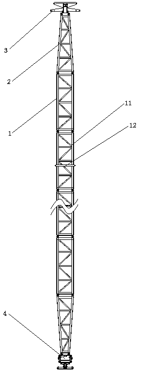
[0016] Such as figure 1 , 2 As shown, the UHV iron tower assembly pole of the present invention includes a straight section 1 , a cone section 2 , a rotating lifting head 3 and a lower supporting cap 4 .

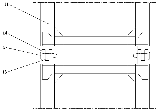
[0017] The straight section 1 is composed of a plurality of single-section straight sections 11 connected end to end; wherein, the middle section of each single-section straight section 11 is matched with a waist ring 12, and the four corners of the top are vertically protruding upwards and provided with four plug-in blocks. 13. Four sockets 14 protrude vertically downward from the four corners of the bottom end; the middle part of each socket block 13 is penetrated with a socket hole along the horizontal direction; each socket 14 is matched vertically from the center of the bottom A slot is provided, and the middle part of the groove wall on both sides of the slot is also provided with an insertion hole along the horizontal direction. The top of each single-section straig...


PUM


Abstract

The invention relates to an extra-high voltage iron tower assembly lifting pole comprising a straight segment, a conical segment, a rotary lifting head and a lower bearing cap. The straight segment isformed by connecting at least two single straight sections end to end. An inserting-connection block is arranged at the top end of each single straight section. An inserting-connection seat is arranged at the bottom end of each single straight section and is provided with an inserting slot matched with the corresponding inserting-connection block. The top end of each single straight section is connected with the inserting-connection seat at the bottom end of the upper adjacent single straight section through the corresponding inserting-connection block in a matched inserted mode and is matched with a horizontal hinge pin for connection fixing. The bottom end of each single straight section is connected with the inserting-connection block at the top end of the lower adjacent single straight section through the corresponding inserting-connection seat in a matched inserted mode and is matched with another horizontal hinge pin for connection fixing. Installation is conducted with the extra-high voltage iron tower assembly lifting pole, labor and time are saved, assembly efficiency and precision are high, manual assembly errors can be reduced effectively, the iron tower assembly periodis shortened effectively, construction efficiency is improved, use is safe and reliable, and life is long.

Description

technical field [0001] The invention relates to the technical field of ultra-high voltage iron towers, in particular to a pole for erecting an ultra-high voltage iron tower. Background technique [0002] As my country enters the era of UHV power grids, UHV transmission projects have been intensively started in recent years, and the important link is the construction of UHV iron towers. At present, the straight sections and cone sections of the poles are basically connected by flanges. The flanges are connected with 20∽12 bolts. The bolt connection is time-consuming and laborious. The bolts need to be tightened twice during the pole assembly process. The conventional bolt connection of the pole-holding flange has defects. Due to the characteristics of axial force, if the pole is deflected by 0°~15° (within the allowable range), the pole will bear a certain bending moment. At this time, half of the connecting screw on the flange will be under tension and half under compression ,...

Claims


Application Information

Patent Timeline
Patent Type & Authority Applications(China)
IPC IPC(8): E04H12/08E04H12/34
CPCE04H12/08E04H12/34
Inventor 张卫民王艳华
Owner 张卫民
Why Eureka
Try Eureka