
Method for testing laser damage threshold of optical thin film

A laser damage threshold, optical thin film technology, applied in the field of optical detection, can solve the problems of urgent optical thin film, time-consuming, complicated operation steps, etc., and achieve the effect of saving the number of test samples and test time, and high applicability

Active Publication Date: 2019-12-06
SHANGHAI INST OF OPTICS & FINE MECHANICS CHINESE ACAD OF SCI
View PDF9 Cites 7 Cited by
  • Summary
  • Abstract
  • Description
  • Claims
  • Application Information

AI Technical Summary

Problems solved by technology

The operation steps of this method are cumbersome. Under a specific number of laser pulse irradiation, it is necessary to test multiple energy steps, and each energy step needs to test multiple points to find the maximum energy density of zero-probability damage. time, and when a large number of test samples are required
[0004] Because the existing damage testing methods for optical thin films under multi-pulse irradiation of femtosecond laser are difficult to ensure the efficiency and accuracy of the damage threshold test of optical thin films, therefore, a simple, efficient and accurate method for multi-pulse irradiation of femtosecond laser is proposed. Damage Threshold Testing Requirements for Illuminated Optical Films Are Increasingly Urgent

Method used


Image

  • Method for testing laser damage threshold of optical thin film
  • Method for testing laser damage threshold of optical thin film
  • Method for testing laser damage threshold of optical thin film

Examples


Embodiment 1

[0038] This embodiment implements a laser damage threshold testing system for an optical thin film.

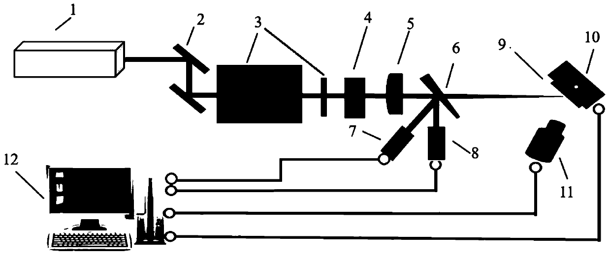
[0039] figure 1 A schematic structural diagram of a laser damage threshold testing system for optical thin films is shown.

[0040] figure 2 A computer structure schematic diagram of a laser damage threshold testing system for an optical thin film is shown.

[0041] Such as figure 1 , figure 2Shown is a laser damage threshold test system for optical thin films, the test system includes a femtosecond laser 1, two mirrors 2, an energy attenuation system 3, a mechanical shutter 4, a focusing lens 5, a wedge 6, a beam quality analyzer 7, Energy meter 8, two-dimensional mobile platform 10 for optical film placement, CCD camera 11, computer 12, above-mentioned computer 12 is provided with data output card 13, motion control card 14; Above-mentioned femtosecond laser 1 is connected to data output card 13, above-mentioned The two-dimensional mobile platform 10 is connected to t...

Embodiment 2

[0043] This embodiment implements a method for testing the laser damage threshold of an optical thin film.

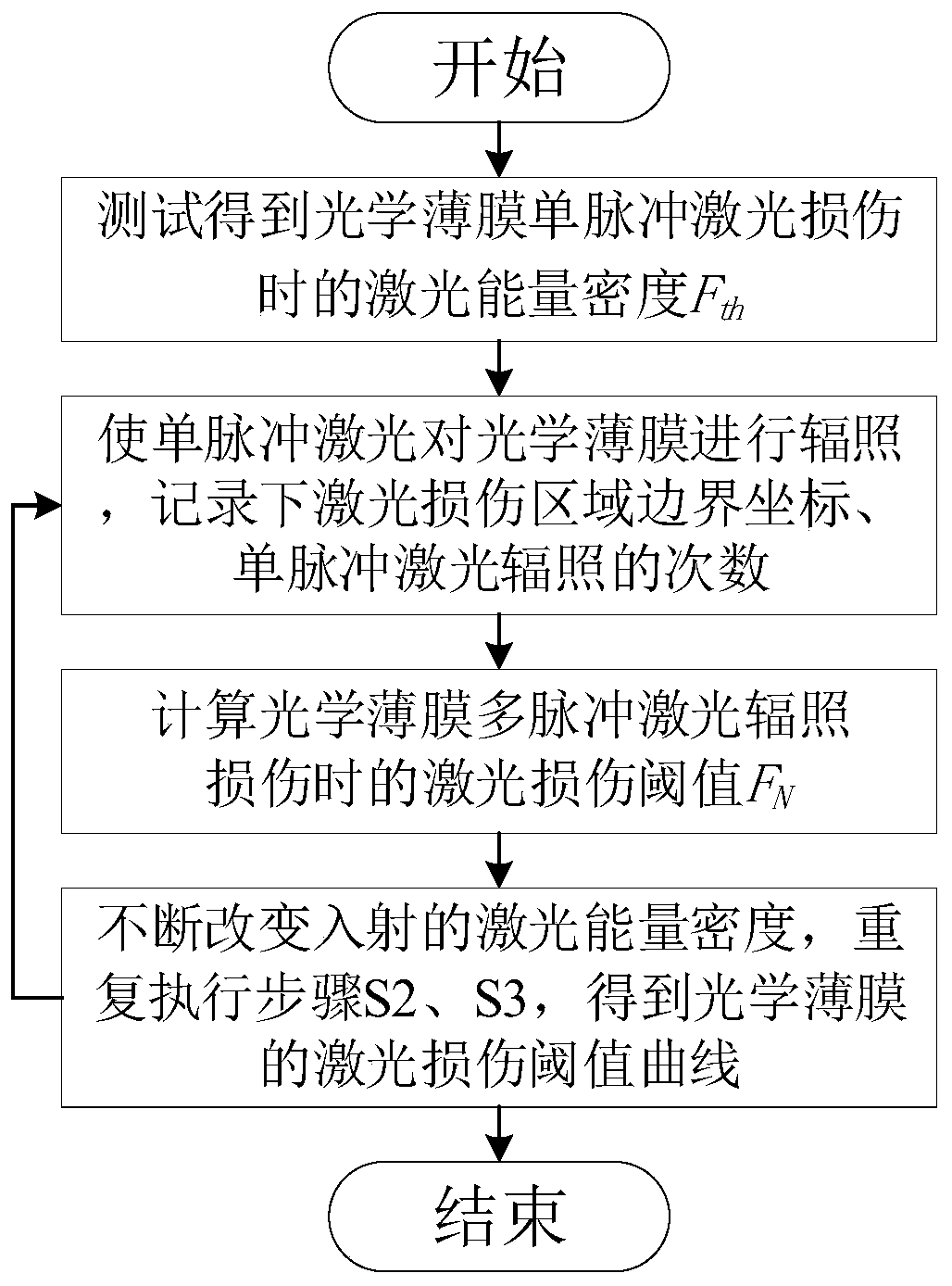
[0044] image 3 A step diagram of a method for testing the laser damage threshold of an optical thin film is shown.

[0045] Such as image 3 As shown, a method for testing the laser damage threshold of an optical thin film, the above-mentioned test method runs on the above-mentioned test system, and includes the following steps:

[0046] S1. Adjust the incident laser to a single pulse laser, move the optical film 9 to the position of the laser spot, adjust the peak laser energy density of the incident single pulse laser from high to low, and use the 1-on-1 mode to test to obtain a single pulse of the optical film 9 Laser energy density F during laser damage th ;

[0047] S2. Adjust the laser energy density of the incident single pulse laser to be lower than F th a certain value of F 0 , adjust the mechanical shutter 4 to be in a normally open state, so that the s...

Embodiment 3

[0064] This embodiment is a method for testing the laser damage threshold of an optical thin film under multi-pulse irradiation of a femtosecond laser. This embodiment is a specific application of Embodiment 1 and Embodiment 2.

[0065] A method for testing the laser damage threshold of an optical thin film under multi-pulse irradiation of a femtosecond laser, the method comprising the following steps:

[0066] Step 1, the computer 12 controls the laser output of the femtosecond laser 1 through the data output card 13, and the laser beam output by the laser 1 reaches the energy attenuation system 3 after passing through two reflectors 2, and the described laser can be transferred by controlling the energy attenuation system 3 1 The output Gaussian laser energy density is adjusted to 0.2J / cm 2 ~0.5J / cm 2 , and then set the number of pulses output by the laser 1 through the mechanical shutter 4 as a single shot, the laser pulse reaches the wedge plate 6 after passing through t...


PUM


Abstract

The invention relates to a method for testing a laser damage threshold of an optical thin film. The method comprises the following steps: S1, obtaining laser energy density Fth of the optical thin film during single-pulse laser damage through test; S2, irradiating the optical thin film by the single-pulse laser, recording laser damage area boundary coordinates (xi, yi) when the laser damage boundary on the surface of the optical thin film is not increased any more, and meanwhile, recording the number n of times of single-pulse laser irradiation; S3, comparing Gaussian distribution of the laserenergy density with laser damage area distribution to obtain a laser damage threshold FN of the optical thin film during multi-pulse laser irradiation damage; and S4, continuously changing the incident laser energy density, and repeatedly executing the steps S2 and S3 to obtain a laser damage threshold curve of the optical thin film under the irradiation of femtosecond laser with different pulsenumbers. The method has the beneficial effects that the measurement accuracy of the laser damage threshold of the optical thin film under multi-pulse laser irradiation is guaranteed, and meanwhile, the test efficiency of the damage threshold of the optical thin film under multi-pulse laser irradiation is greatly improved.

Description

【Technical field】 [0001] The invention relates to the field of optical detection, in particular to an optical film damage threshold testing system and a method thereof. 【Background technique】 [0002] The damage to optical films by strong lasers restricts the development of lasers to high power and high energy, and is also an important factor affecting the stability, reliability and service life of optical films. With the continuous expansion of the application range of ultra-intense and ultra-short lasers, the importance of the damage resistance of optical thin films or optical components has become increasingly prominent, and accurate and efficient testing of the damage threshold of laser thin films is a prerequisite for improving the damage resistance of laser thin films. In recent years, the International Standardization Committee has promulgated ISO11524-1 and ISO11524-2, which are international standards for damage to optical components caused by laser light. [0003]...

Claims


Application Information

Patent Timeline
IPC IPC(8): G01N21/84G01M11/00
CPCG01N21/8422G01M11/00
Inventor 赵元安马浩邵建达李大伟刘晓凤邵宇宸李成李婷
Owner SHANGHAI INST OF OPTICS & FINE MECHANICS CHINESE ACAD OF SCI
Learn More