Liquid cooling system of power battery and control method of liquid cooling system of power battery

A power battery and control method technology, which is applied to secondary batteries, circuits, electrical components, etc., can solve the problems of different charging and discharging capabilities of batteries, lowering the temperature of battery boxes, and temperature instability, so as to improve insulation and battery stability. Capability and service life, narrow temperature difference range, and good temperature consistency

Pending Publication Date: 2019-12-06
江西优特汽车技术有限公司
View PDF10 Cites 3 Cited by
  • Summary
  • Abstract
  • Description
  • Claims
  • Application Information

AI Technical Summary

Problems solved by technology

Since each battery cell is installed in a different position in the battery system, and it is impossible to be completely consistent when it is manufactured, its heat generation and heat dissipation capabilities are also different, and there will be a large temperature difference between the individual cells. phenomenon, which will lead to the temperature inconsistency of each cell
Due to the large temperature difference of the battery cells, the charging and discharging capabilities of each battery cell are different, and the performance of the battery system can not reach a good level.
[0003] As far as the existing technology is concerned, in order to remove a large amount of heat in the battery, a liquid cooling system device is generally used, but today's liquid cooling system has many shortcomings, such as the flow channel size of the liquid cooling device is the same, and the degree of heat dissipation is the same, so the temperature distribution of each battery cell No change, that is, the temperature of the high-temperature battery is still very high, and the low temperature is still very low. Such a liquid cooling system can only reduce the temperature of the battery box, but cannot narrow the temperature difference between the batteries, which will affect the batteries and batteries. System performance and life
[0004] Moreover, the liquid cooling system in the prior art has only one external circulation flow, but the temperature of the external circulation itself is unstable, and when the temperature of the battery box is lower than the preset value, it does not need to dissipate heat, and the heat distribution in the battery box may severely uneven

Method used


Image

  • Liquid cooling system of power battery and control method of liquid cooling system of power battery
  • Liquid cooling system of power battery and control method of liquid cooling system of power battery

Examples


no. 1 example

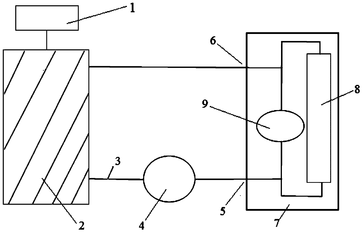
[0038] The first embodiment, such as figure 1 Shown:

[0039] In order to overcome the defects of the prior art and achieve the purpose of the invention to improve the temperature consistency of the battery core, the technical solution adopted by the present invention is:

[0040] Such as figure 1 As shown, in the liquid cooling system of the power battery of the present invention, the battery box 7 is provided with an internal circulating water channel, which communicates with the two pipes 3 connected to the radiator 2 .

[0041] A small water pump 9 is set on the internal circulating waterway. A small water pump 9 with very small power and volume is installed inside the battery box 7, and the temperature of the battery box when the liquid cooling system is turned on is preset at 35°C or the temperature difference of the battery cells is 5°C. That is: the preset temperature is 35°C; the preset temperature difference is 5°C.

[0042] The small water pump 9 is installed in...

no. 2 example

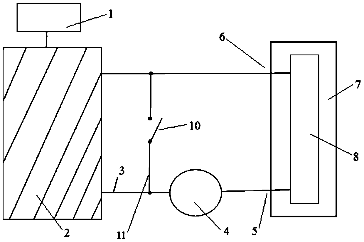
[0051] Second embodiment, such as figure 2 Shown:

[0052] The present invention also provides a liquid cooling system for a power battery, the power battery includes a battery core 8 arranged in a battery box 7, the liquid cooling system includes an expansion tank 1, a radiator 2 and an external circulation water pump 4, The radiator 2 is respectively connected to the liquid inlet 5 and the liquid outlet 6 of the battery box 7 through two pipelines 3; the two pipelines 3 are connected through an intermediate pipeline 11; Temperature control switch 10.

[0053] A temperature control switch 10 is added, which is connected with the battery box before the water pump. The temperature control switch 10 can be connected with a temperature control switch 10 between the front of the external circulation water pump 4 and the liquid outlet 6 when the small water pump 9 is not installed in the battery box 7 .

[0054] When the temperature difference of the battery core 8 in the batte...


PUM


Abstract

The invention discloses a liquid cooling system of a power battery, and the power battery comprises a battery cell arranged in a battery box. The liquid cooling system comprises an expansion water tank, a radiator and an external circulating water pump, wherein the radiator is connected with a liquid inlet and a liquid outlet of the battery box through two pipes; an internal circulating water pathis arranged in the battery box and is communicated with the two pipes connected with the radiator. The invention further provides a control method of the liquid cooling system. According to the abovetechnical scheme, the liquid cooling system is designed into two controls of internal circulating and external circulating of the battery system by taking the battery box as a reference object, the temperature is controlled by the outer circulating, and the temperature difference is controlled by the inner circulating, so that the temperature of the battery box does not exceed a preset value, thetemperature difference range among the battery cell can be reduced, the temperature consistency in the battery cell is better, the insulativity of the battery pack is improved, and the capacity and the service life of the battery are prolonged.

Description

technical field [0001] The invention belongs to the technical field of automobile power battery structure. More specifically, the present invention relates to a liquid cooling system for a power battery. In addition, the present invention also relates to a control method of the liquid cooling system. Background technique [0002] The battery system is mainly composed of many battery cells connected in series and parallel. When the battery cells are charged and discharged, a large amount of heat will be generated, which needs to be dissipated in time through the cooling device. Otherwise, the performance of the battery system and the vehicle system will be affected if the temperature is too high. and safe. Since each battery cell is installed in a different position in the battery system, and it is impossible to be completely consistent when it is manufactured, its heat generation and heat dissipation capabilities are also different, and there will be a large temperature di...

Claims


Application Information

Patent Timeline
Patent Type & Authority Applications(China)
IPC IPC(8): H01M10/613H01M10/617H01M10/625H01M10/633H01M10/6556H01M10/6568
CPCH01M10/613H01M10/617H01M10/625H01M10/633H01M10/6556H01M10/6568Y02E60/10
Inventor 李世明徐秋鹏
Owner 江西优特汽车技术有限公司
Why Eureka
Try Eureka